Solenoid: Directional Control Valves – Everything You Need To Know
Post By: Tom Rowse On: 21-06-2022 Read Time: 5 minutes - Guides - Pneumatics
Post By: Tom Rowse On: 21-06-2022 Read Time: 5 minutes - Guides - Pneumatics
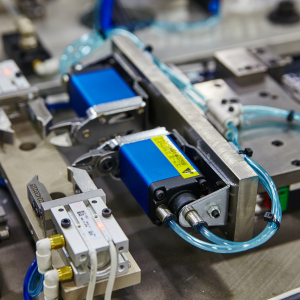
In any pneumatic system, compressed air is passing from one point to another. This is usually in order to achieve movement of a mechanical part such as a pneumatic cylinder or actuator. This part will move forward and back, or up and down, but in whichever plane the actuator is moving it will need to be controlled by the flow of the compressed air. This is why many pneumatic systems contain a solenoid valve, also known as a directional control valve (DCV). There’s increasing reliance on pneumatics as a cleaner use of energy, and DCVs are becoming correspondingly more widespread and more efficient.
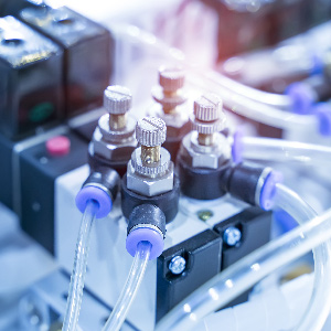
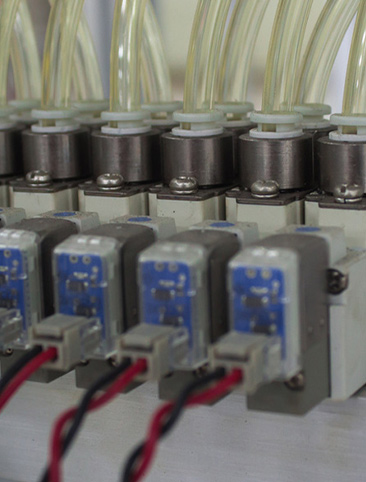
Solenoid valves work by means of an electrical coil, activated by a signal sent from a controller or PLC. This controls the position of a spool or plunger which opens or closes the relevant valve, enabling directional control of the airflow. This, in turn, drives the actuator and the equipment to which it is attached. A pneumatic system may have several DCVs in use. They can be configured with a variety of different control options, according to the number of input and output ports they have.
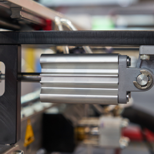
A solenoid valve or DCV consists of the valve housing or body, generally made of aluminium, with selected holes machined into it. These are the ports, which correspond to the pathways inside the housing through which the air will pass. They also connect externally to the cylinder. The body of the solenoid valve also houses the moving part that mechanically opens or closes those different pathways. This part is usually called the spool. Movement of the spool inside the housing is controlled by an electric solenoid and a spring on the opposite side. The valve is bidirectional, since air can flow through it in both directions.
The simplest form of solenoid valve is a 2/2 valve. Directional valves always have two numbers. The first number indicates how many ports there are, and the second shows how many states the spool can be in. So the common 2/2 valve is designed with two ports (In and Out) and can be in either of two states (Open or Closed). This type of valve is commonly called a shut-off valve. There are also valves with three or five ports (still offering two states) and a 5/3 valve with three possible states. This means that a double-acting cylinder, for example, can be stopped in an intermediate, centre position for more complex operations.
There are commonly two types of solenoid valve used in pneumatic systems. A single-acting or monostable valve is held by the spring in its home or rest position, which can be Normally Open (NO) or Normally Closed (NC). As soon as the solenoid receives the command signal from the PLC, it will switch the valve into its energised state, moving the spool so that the spring is compressed. Protrusions on the spool move over to block or unblock passage to the ports, to control the direction of the airflow and actuate the cylinder. Once the electrical signal ceases, the power is released, so the spring will push the spool back and return the valve to its rest position.
In the most typical, single-acting solenoid valve, the spool remains in the active position as long as the PLC continues to send the command signal, and the directional control of the compressed air keeps the cylinder in its last position. As soon as the command signal from the PLC ceases, the spring pushes the spool back to its original position and the direction of the airflow is changed. Exhaust air behind the piston gets purged via the valve's exhaust port into the atmosphere.
Double-acting or bistable solenoid valves have a solenoid on each end of the body. Each one is responsible for a momentary impulse that switches the valve to a single state, where it remains in position. When the signal is stopped, there is no spring to return the valve to its rest position, so the second solenoid must perform this function.
Uses of pneumatics are many and varied, but it's important to keep the design and structure of the components to a recognisable standard. To this end, there are a number of standardised pneumatic symbols that are used in circuit diagrams to represent the various parts, including all the different types and configurations of valve. These symbols have been agreed upon and are governed by the International Standards Organisation under ISO 1219-1:2012.
When representing a solenoid valve as a symbol, it's drawn as a single square for each state of its operation. A 2/2 valve has just the two (Open or Closed) states, so it's drawn as two adjacent squares. In each square, there are directional arrows showing the airflow between the available ports. The solid line indicates which ports are connected and the arrow indicates the flow direction.
The ports are numbered, with a 'T' symbol on the square indicating closed ports. On the more complex 5/2 solenoid valve, such as those used to control double-acting cylinders, the valve offers five ports and can be in two states. This type of cylinder requires two outlet ports and can be mono- or bi-stable.
On both sides of the two (or occasionally three) squares, an actuator symbol is added, which shows which square is active. A solenoid symbol depicted on the left-hand side of the valve indicates that this square has been energised and is in the active state. A spring symbol depicted on the right-hand side of the valve shows that the valve is now in the rest state.
With many more industries adopting pneumatics as their primary drive, it's important to understand the use and workings of solenoid valves and their value in directional flow control. Learning to read the different symbols can be confusing at first, but they allow the equipment and its various components to be universally recognisable.