The Ultimate Pneumatics Guide
Post By: Ryan King On: 19-02-2019 Read Time: 19 minutes - Guides - Pneumatics
Post By: Ryan King On: 19-02-2019 Read Time: 19 minutes - Guides - Pneumatics
Industry 4.0 is changing the traditional way that manufacturing and production are accomplished, and a positive turn towards clean energy means that more and better air-driven components are available. Advanced electronics, AI and micro-components have all helped to enhance the control capacities for pneumatic systems, giving them much more precision and efficiency than ever before.
Pneumatics is the branch of engineering physics that manipulates the energy in a compressed gas to carry out mechanical tasks. Its origins date back to pre-history, when people used their lungs to ignite fire by blowing on sparks, or to shoot out darts through a tube. The word itself derives from the ancient Greek word ??????, meaning "a blowing", from the verb to blow, also associated with lungs (as in pneumonia). The first industries in the Bronze Age (from 3200 BCE) improved on the human lung, devising a bellows made from animal skin to intensify the heat in a fire for smelting.
A standard pneumatic system uses a motor-driven air compressor to reduce the volume of atmospheric air by about half, and increase its pressure to approximately double. The pressurised air travels through a system of valve-controlled pneumatic hoses to the cylinder. This potential energy can then produce kinetic energy, using either rotary or linear motion to control some form of mechanism – like an assembly line for processing or packaging, or directly connected tools such as air springs, grippers and robotic arms.
There are five basic items required to compress the air, store it, control its flow, move it around and use it. These are, sequentially:
The main reason that so many manufacturers choose pneumatic systems is that while the average running costs may be higher, the initial installation and subsequent maintenance are both still cheaper and easier. It will always depend on what particular application is being configured, but with electrical systems becoming cheaper and pneumatics more efficient, it is an increasingly delicate balance.
Many heavy-duty industrial applications require very large amounts of force to move a load, with pressures of several hundred bar, such as stampers, crushers, presses, lifts, cranes and gantries. Electrical systems are generally not capable of developing the amount of force these applications require. Pneumatics are similar to hydraulics in their ability to develop higher levels of force, but compressed air is more versatile than water or oil. Compressed air energy also expands vigorously when it is released, allowing a considerable volume of air to be moved through valves and cylinders, so that pneumatic actuators can achieve great velocities.
Although electricity may still be faster, modern pneumatics have improved their overall speeds to at least 50% of that achievable with electricity, at a far greater pressure. In the appropriate circumstances, pneumatically actuated machinery can be surprisingly quick and snappy, making it a good choice for light production tasks in manufacturing and assembly. The application's cycle rate is also a factor, to assess the probable wear and repair, but on the whole pneumatic systems have fewer mechanical components and a longer working life. Clean, dry air is not hard to come by, and replacing simple components such as seals and valves is straightforward and inexpensive.
As well as developing force, air is naturally compressible and therefore often used as a system for absorbing excessive shock, which is generally useful for smaller loads at lower pressures. Applications using integrated shock absorbers with pneumatic position cushioning can handle larger loads at double the speed, with end position accuracy of 0.05mm. Pneumatic shock absorbers in a cylinder employ spring-loaded valves or electronic sensors to control the air flow, and are used effectively in aerospace applications and the food and beverage industry. Operational sound levels are also becoming less of a problem, with design improvements such as silencers reducing clatter and exhaust venting noise.
Sensitive and very delicate applications such as milking, handling eggs or moving sheet glass can also be driven by pneumatics, using a system of vacuum generators and suction cups. In modern manufacturing, automation processes are often a combination of advanced pneumatic technology and solenoid valves, plus pressure switches and position sensors.
Some useful characteristics can be compared directly between pneumatic and electrically driven systems for the production of linear motion.
Peak power – Both pneumatic and electric systems offer reasonably high peak power.
Size – Pneumatics have a low size/force ratio, while electrics offer medium size/force.
Complexity – Pneumatics are simple in construction, while electric systems are of medium to high complexity.
Speed – Electricity still has the edge over pneumatics, but the gap is getting smaller.
Control – Pneumatics operate by simple pressure valves, while electrical systems generally use an electronic controller, though the distinction is not so cut and dried these days.
Positioning Accuracy – Pneumatics are less precise than electrical systems, but again, modern developments are improving pneumatic positioning systems.
Purchase Cost – Pneumatic systems are still currently cheaper to buy than electrically-driven systems, but costs of the latter are diminishing.
Operating Cost – The running costs of a compressed air system are still higher than those using electricity.
Maintenance Cost – Pneumatics cost about the same to maintain as electric systems.
Reliability – Pneumatics are still regarded as much more reliable than electrical systems, especially in the event of power cuts.
Efficiency – Conversely, electricity is regarded as a more efficient energy supply than air.
Utilities – Electrically-driven systems require only the supply of electricity, while pneumatics require both a compressor, the power to run it and the pipework to connect it.
Maintenance – Pneumatic systems require low maintenance and little specialised knowledge to carry out repairs, whereas electrical systems require more expertise and more frequent maintenance.
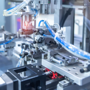
Tooling and parts in industrial machinery are often best moved in a linear fashion by pneumatic power. One of the most common of these is the typical pick-and-place action, requiring both vertical and horizontal travel, a position stop and some form of gripper. They are also widely used for part positioning or clamping functions, and the lifting and shifting of items to be assembled or packed. Wherever machine tooling is required to move, force to be applied, or a part required to be held, sorted or stacked, pneumatic systems will probably have a solution, especially with the recent developments in servo-pneumatics. This multiplicity of tasks can also be expanded for more precise positioning with closed loop control, which allows for more complex activities such as cutting and crimping, embossing, labelling and tensioning.
There are so many common uses of pneumatics that most people will have encountered them at some point, even if it was only the dentist's drill. Then there are the pneumatic drills used in road-building and the pile drivers used in large-scale construction. Most mechanics employ pneumatic tools such as jacks and socket wrenches to change tyres, and they form part of the braking system for many large vehicles. The automotive industry as a whole has always been a leader in pneumatic engineering, but pneumatic seals are also particularly important for manufacturing and packaging equipment in the cheese industry, for example.
The wood industry uses pneumatic machine tools extensively for cutting, sawing, sanding, boring holes and fastening screws, and textiles can be spun and woven using pneumatic rams and seals. Metal-working and panel-beating applications deploy pneumatic sandblasters, grinders, riveters, paint scrapers, shakers and sprayers, and nail guns can be used for all sorts of activity. In mining operations on land, pneumatics are employed in roof-supporting machinery, although hydraulics are generally used for the drilling process. Pneumatics are also important in the metal die-casting industry, manufacturing machine parts and metal components of all types.
Low-pressure devices using pneumatic control are also increasingly used as an alternative to electrical relays in the process control industry. Commercial air systems have undergone major changes in their design and construction, so that it is now common to find air as the primary power, controlled by programmable electronic devices, such as PLCs.

A properly commissioned and configured pneumatic system has many advantages over other types of automation. For example, pneumatics doesn't rely on a complex configuration of mechanical gears, shafts, cams or levers, nor need to overcome inertia in order to start up. Motion can be initiated and transmitted continuously and smoothly, without having to account for the slack that is inherent with solid machine parts.
Similarly, air doesn't break or wear out parts, as there is no friction and consequently much less necessity for repair or replacement of moving parts. Air is always there, readily available and capable of storage in a tank for transportation and use in a remote area. Many mobile applications deploy pneumatic motors, because compressed air can be easily conveyed on heavy-duty transport vehicles. Pneumatic cylinders are used on the roads for positioning paint nozzles for line painting vehicles, for example, for pumping equipment on salters and spreaders, and for controlling tail gates and tarpaulin covers on large lorries.
Widely variable motion is enabled by both linear and rotary power transmission. The force developed by the potential energy of compressed air can be conveyed in any direction, as air has no fixed shape and will fill any cavity. It can be directed vertically, horizontally, diagonally and even round corners, with relatively little loss of efficiency and no complex delivery mechanisms. These forces can also be transmitted rapidly over a considerable distance, so it is even possible to disperse the different components of an automated pneumatic system over a wide area. There are no return lines required in pneumatic systems, because there is no need for discharged air to be returned for the system to keep on functioning.
Size matters, and pneumatics has the edge in the ability of smaller forces to control much larger ones, through regulators and pilot air controllers. Power transmission is also achieved through much smaller pipes and orifices, and the overall size of pneumatic systems is comparatively compact. Some applications even use miniaturised pneumatic actuators, where constraints of size and weight may apply or there is a greater precision requirement. Applications that demand such parameters include analytics and test equipment, animatronics and semiconductor manufacture, ink-jet printing, HVAC systems, and many more.
If a pneumatic system is properly configured and adapted to its allotted task, it will deliver smooth and uniform action, flexible enough to accommodate load variations and free of vibration. It is protected against excess strain or breakdown by safety components such as automatic pressure release valves, which immediately exhaust the air in the event of an overload. Pneumatic systems are cost-effective, require little manual adjustment and are safe for use in hazardous environments. They function in broad range of temperatures, can be used in high humidity areas without any potential for electrical shock, or in explosive areas without producing dangerous sparks.
There are many diverse components that go towards making up a pneumatic automation system, which can be more or less complex according to individual application demands.

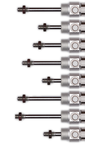
Pneumatic cylinders are designed mostly for linear motion, and are available in both piston rod or rodless actuation. In a single-acting piston rod cylinder, linear motion is enabled in one direction by the compressed air and returned via a mechanical spring for the return stroke. In a double-acting cylinder, the air is manipulated through a more complex series of valves to drive the rod in both directions, allowing for a push-pull motion on the load.
Rodless cylinders come in several types. One is an inflatable bellows, with a single-action elastomer tube capable of creating high force and bending in any direction. The second, more common form is a linear slider, that mounts the load either on a carriage or moves it with a cable-and-pulley mechanism. Actuators can also be magnetically coupled, by means of a piston-mounted magnet, which exerts a magnetic force on the load to make it move. Rotary motion can also be developed by directing air through a vane, whose channels diminish in size, compressing the air and causing an axle to turn. Rodless cylinders are a good solution for high moment loads or those where a long stroke action is required.

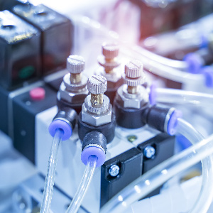
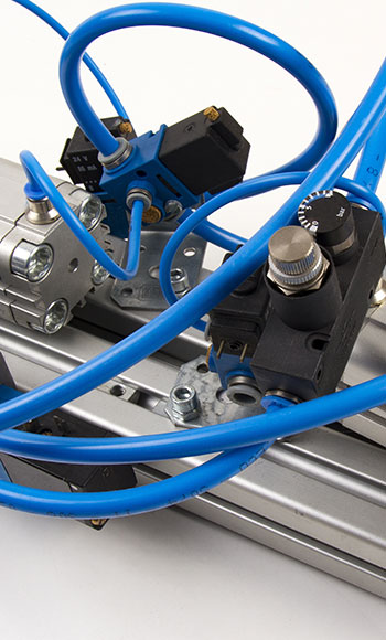
Valves are the essential control mechanism for directing air flow, and come in a wide variety of options to fulfil different functions. On-off valves and soft starts control the start-up procedure, flow control valves regulate the rate of air flowing into various parts of the equipment, while exhaust, shut-off and safety dump valves release air pressure when necessary, especially in the event of an emergency stop. Angle seat valves and ball valves control flow direction, while pilot valves operate a secondary system. Solenoid valves are now frequently used in conjunction with pneumatics, as well as universal valve terminals which allow for modular configuration of increasingly complex systems.

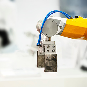
Pneumatic grippers are the type of tool that include jaws or fingers to grasp or enclose an object, for insertion, assembly or transfer in an automated system. Two jaw grippers are most popularly used in parallel or angular configurations, with the parallel type opening and closing only in a plane parallel to the handled object, and the angular type opening wider and requiring more space. Three jawed types handle objects that are multi-sided or spherical.

An air powered, pneumatic, or simply 'air tool' is a generic title for any variety of power tool driven by compressed air, such as sanders, grinders, hammers, drills and wrenches. While the name 'air gun' can also designate an air-powered rifle, it is also commonly used to describe industrial pneumatic tools with a pistol action, such as riveters, staplers and nail guns.

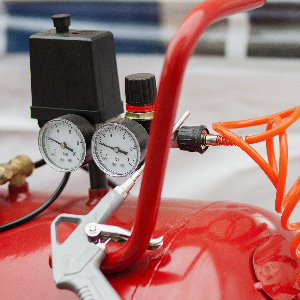
The compression of air heats it up, causing condensation when it cools. Ambient air is also generally impure, containing dust, dirt and other contaminating particulates. If wet and dirty air were to get into downstream components, including hoses, valves and cylinders, it could cause damage and shorten their working life. After filtration, the air must also be monitored to maintain the correct pressure, and often lubricated to protect downstream equipment from dry air damage. While these components are all available separately, they are also frequently combined in a filter-regulator-lubricator unit, or FRL.

The venting of exhaust air can make an explosive sound which causes disturbance. Silencers are designed for addition to an exhaust circuit in order to reduce operational noise levels.

Every pneumatic component requires a steady supply of air which is clean and dry. This is necessary for protection against wear and tear, and to make sure that each part of the system functions as it should. While mechanical motion control may be the primary design focus, this clean, dry air must form part of the commissioning, with sufficient flow to provide the necessary pressure. If there is an inadequate air flow rate it will cause a sag in operating pressure, especially at times when a machine might require a high air flow.
The journey undertaken by atmospheric air to pneumatically-driven machinery is not a simple one, and it can often pick up a lot of unwanted contaminants along the way. Pipes, fittings and multiple devices can all contribute moisture, oil and particulates to the air supply, even when the compressor has built-in filters, dryers, regulators or water removal. To ensure optimal performance, air preparation should still be carried out at the machine itself, especially if there is a long distance between compressor and point of use. Additional water and particulates might still build up, so air preparation should include an FRL unit to filter, regulate and lubricate the air, as well as some form of safety dump valve. This will help to ensure that the equipment is protected as much as is possible from contaminants, and will provide maximum service life. Filter regulator units offer the ideal integrated solution to air preparation, as they save panel space and money if the application runs on one regulated pressure.
The system should be designed with a lockable manual shut-off valve at the front end, to close off the air intake safely for maintenance purposes. Soft start valves can also be installed to cut down start-up clatter, and fulfil the requirement for a safety dump during an emergency stop or other cut-off event. The filter strains the air through some form of mesh in order to trap any solid particles in the air such as dust, rust and dirt. It can also remove any liquids (water or oil) that may have got into the compressed air. Filters come in a broad range of port sizes, usually going from 1/8" to 1", and can be of varying degrees of fineness. Standard filters function on around 40 ?m particulate size, while particulates of 5 ?m or less fine can be removed with finer filters.
The specific requirements of the system must be assessed to determine how fine a filtration is demanded, since too fine a filter can quickly become blocked, while an insufficiently fine filter may damage high speed and precision components. Speciality filters may also be demanded for paints, foods or pharmaceuticals, while aerosols or oil vapours will require a coalescing filter. The filtration unit will have a bowl or sink to collect condensates, often with some form of drain valve (manual, automatic or semi-automatic).
The equipment's design will usually dictate its operating pressure, so the regulator must adjust the pressure of the newly filtered air, to within a typical range of 1-12 bar. Higher precision applications require lower pressure ranges, and piloted valves usually require 8 bar. Machinery must maintain a specified minimum operating pressure, with an integral pressure gauge and sensors to trigger adjustments. Regulators have a pressure relief valve if pressure gets too high or if the set point is reduced, as otherwise the only way to bring the pressure down would be to cycle the equipment.
A lubricator is an integral part of an FRL unit, but may not always be required. Many modern pneumatic devices don’t need lubrication, but high-speed power tools often do, so it's important to check the manufacturers’ recommendations before deciding on a combined FRL or separate components for your system. If only a few system components require lubrication, a smaller, separate unit may be installed, with a needle valve, ejector nozzle or drip which creates a mist of oil vapour in the air. This oil content will affect the ability of the compressed air to travel uphill, so air preparation should be sited above active machinery, and line routing considered carefully.
A properly designed or commissioned air preparation system, with all required components correctly specified, will ensure a longer life of trouble free operation for all downstream pneumatic equipment.

Fittings, tubing and devices all need to fit together, and all come in a wide variety of sizes and types. Push in connectors are popular, and are constructed of metal or polymers like most threaded fittings, though metal threads provide a tighter bond. Compression fittings are commonly used to join together two dissimilar types or sizes of pipe, and barb fittings are good for flexible tubing. Quick connect, disconnect or release fittings, usually of the push in type, are frequently used for air hose couplings, as they enable easy change-over of hose or tool connections and are available in several materials and sizes.
Barb fittings have progressively larger angled flanges as they get closer to the join and are frequently used in flow control for their reliability, performance, convenience and excellent value. The barb is slightly larger than the tube's inside diameter and is simply pushed in, with a clamp often added for additional security. While this type of fitting is easy to use, barbs have a higher risk of popping out under pressure or leaking. Compression fittings join a smaller diameter tube with a ferrule slipped over its outside diameter. This small cylindrical piece is then compressed by a nut that can be tightened on the other piece of tubing. This type of fitting is very secure, but can frequently be difficult to remove as it causes deformity.
Push in fittings easily connect flexible tubing by inserting its end into the connector, which can be released with a circular release ring. They can be made from tough thermoplastic with metal gripping claws and threads, offering an ideal all-round solution for most applications. All-metal push in connectors are made in stainless steel for harsh or sensitive environments, and are also good in high temperatures and for wash-down applications.
Selecting and installing numerous fittings and combining them with appropriate tubing can be a mind-bender, and it's common to miss something along the way. Tubing and hoses offer a similar array of choices for modern pneumatic systems, but it's important firstly to differentiate the two: hoses are usually reinforced in some way for high pressure applications, while tubing is unreinforced and used for lower pressure or gravity flow applications. Flexible pneumatic hose or tubing is more common than rigid, as it offers more configuration options, but both are available in many different types. It should also be remembered that tubing is specified by its outside diameter (OD) and hose by inside diameter (ID), and both come in metric and imperial measurements, so that continuity must be carefully observed between the two systems.
Flexible hoses and tubing are strong and kink-resistant, and can be supplied in coils for moveable equipment. Modern materials are finely tuned for specific applications, especially if any kind of foodstuff or chemical is involved, and they are frequently colour-coded for easier identification.
Most problems with pneumatic systems arise out of misguided attempts to make the system elements perform beyond their design parameters.
Pneumatic systems are a versatile, cost-effective and rapidly advancing technological solution to the manufacturing and production demands of Industry 4.0. They produce clean kinetic energy from readily available potential energy, and are a safe and economical alternative to electric motors. Next generation developments combine to produce innovative solutions, including miniaturisation and servo-pneumatics, which vastly improve positioning capabilities.
When it comes to commissioning and designing pneumatic systems, there are many types of configuration and components, and each application's requirements must be carefully considered. When air is properly supplied, prepared and distributed, however, pneumatic devices and actuators will function optimally over a long service life, with limited operational problems and minimal maintenance required.