Pneumatic Symbols
Post By: Ryan King On: 16-05-2019 Read Time: 22 minutes - Guides - Pneumatics
Post By: Ryan King On: 16-05-2019 Read Time: 22 minutes - Guides - Pneumatics
Symbols are used as a system of shorthand iconography that’s shared within an industry or functional system across the world – like traffic lights. Drivers everywhere know that red means stop and green means go. Pneumatic symbols are simply that specific set of symbols which have been devised for use in the pneumatics industry.
Having a universally understood pneumatic symbology means that the operation and functionality of particular components and machinery can be effectively described to anyone, anywhere, as long as a consistent system is used for the icons. This makes it much easier for manufacturers and operators of machinery to identify individual parts and recognise their function. It also facilitates the diagnosis and repair of faults. With today's technologies, this can even be carried out remotely, just by sending a snapshot of the component in question to a service engineer.
Pneumatic systems are created and operated in accordance with international standards, so as to make their manufacture reliable and consistent. The International Organisation for Standardisation (ISO) is an independent, non-governmental body. It’s responsible for establishing universally agreed rules for the design, specification and construction of commonly used materials, objects and technology. These standards govern everything down to the smallest screw, and include the commonly used paradigms for documentation. In particular, ISO 14617 deals with the graphical symbols that are universally used in diagrams.
ISO 1219-1:2012, which is a sub-division of the ISO 14617 series, lays down the basic elements required to produce such universally recognised symbols. This standard established the rules for creating symbols specifically related to fluid power systems, i.e. hydraulic and pneumatic systems. Symbols used in pneumatic air supply and distribution are designed to illustrate the function of valves and other necessary devices in the system.
Pneumatic symbols were principally created to identify components on circuit design diagrams, but they can also be used on the components themselves. On a valve, for example, there will be a manufacturer's label carrying pressure and power information, as well as a small diagram of how many ports and outlets it has and how they work. The fixed dimension ratios of the diagrams may be slightly variable, as they were originally intended solely for use in data processing.
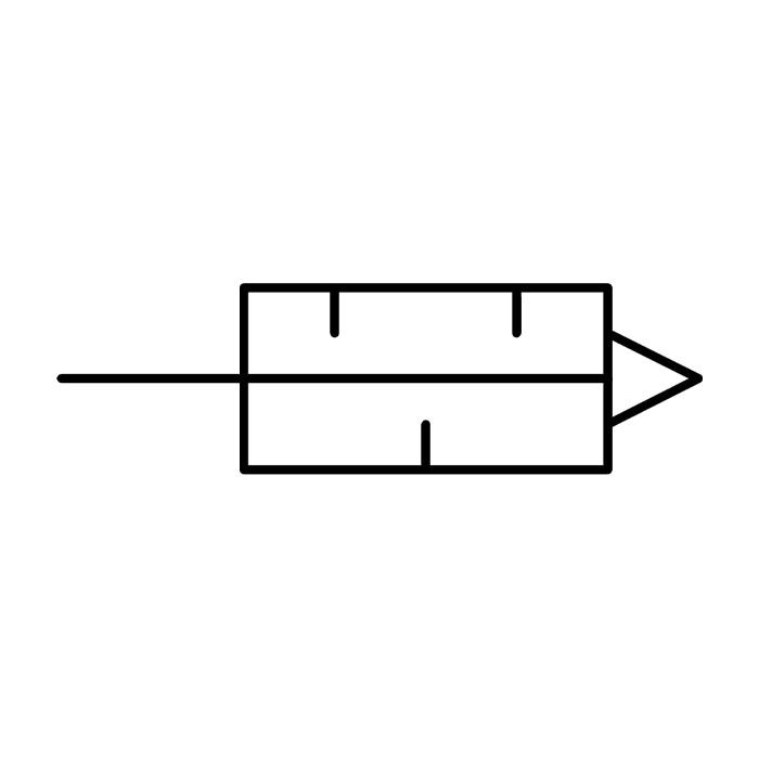
Pneumatic cylinders are designed on several different operating principles, which are split broadly into piston rod or rodless actuation. Double-acting cylinders drive the rod back and forth, allowing a push-pull load motion, while single-acting cylinders use a return spring with only the outstroke moving the load.
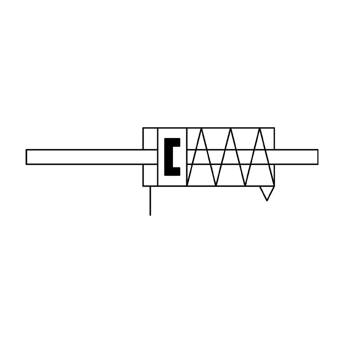
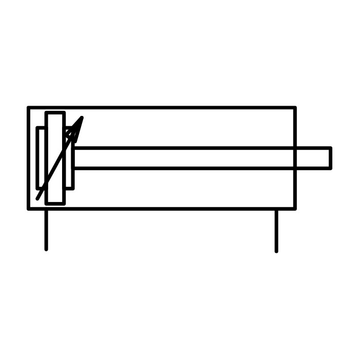
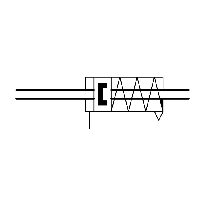
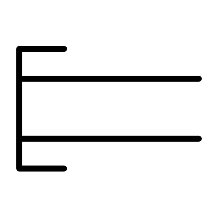
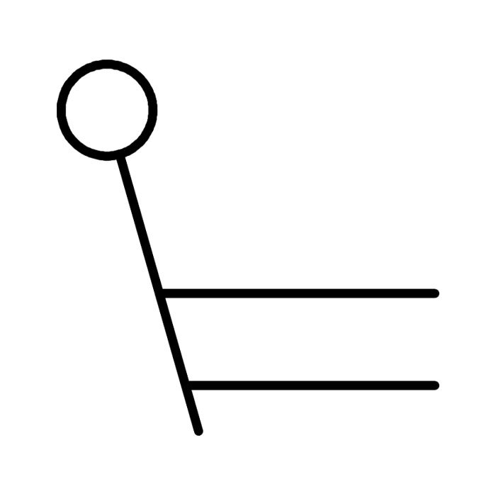
In a single-acting cylinder, compressed air is used to push the piston out, and a spring to return it (instroke). In a single-action rod type, compressed air entering through a port at one end of the cylinder extends the piston rod (outstroke), the output connection moves the load, the air is exhausted when the valve is turned off. The rod's extension speed depends on the rapidity of the exhaust. Single-acting cylinders can have the spring mounted at either the front or rear depending on the application.
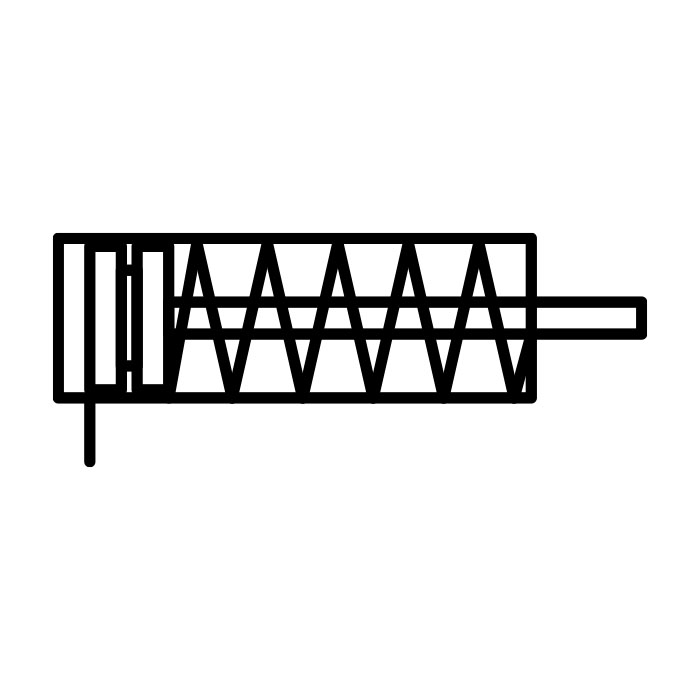
Single Acting Cylinder, Front Spring
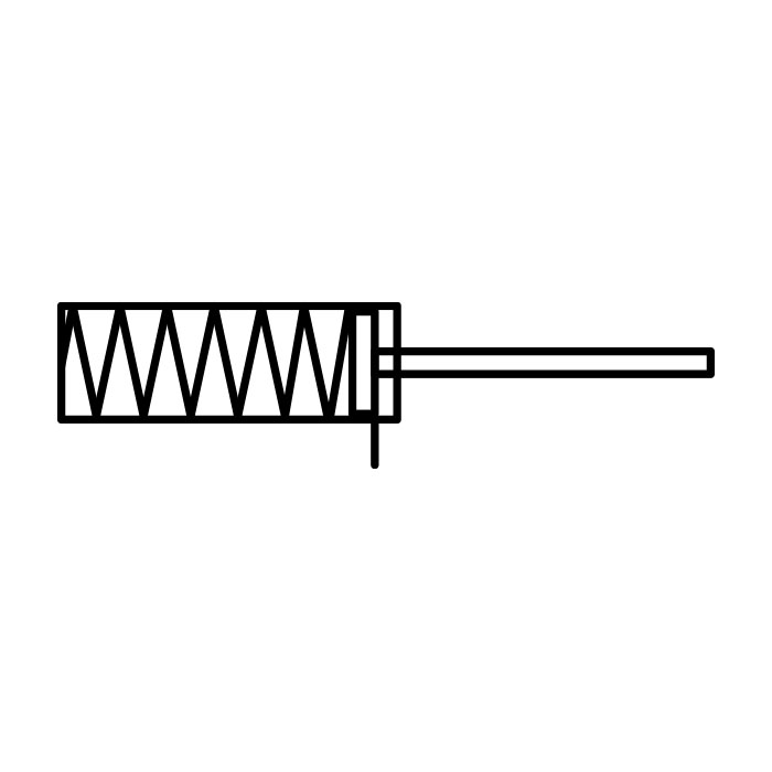
Single Acting Cylinder, Rear Spring
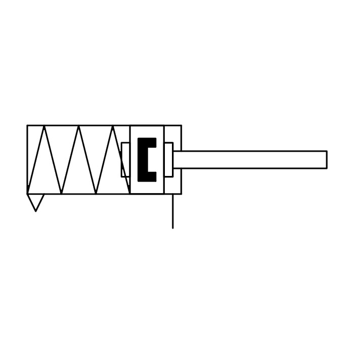
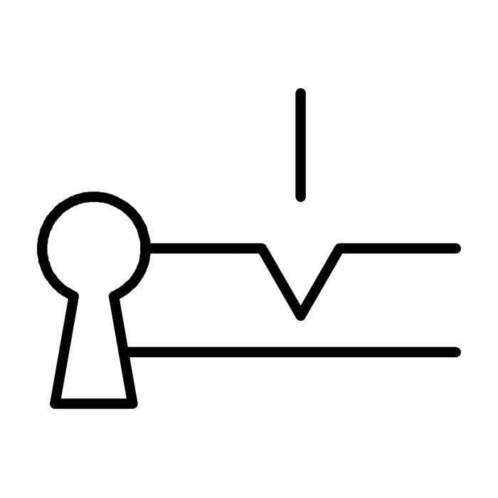
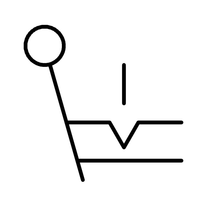
Single Acting Cylinder, Rear Spring with Position Sensing
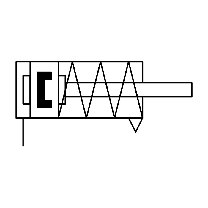
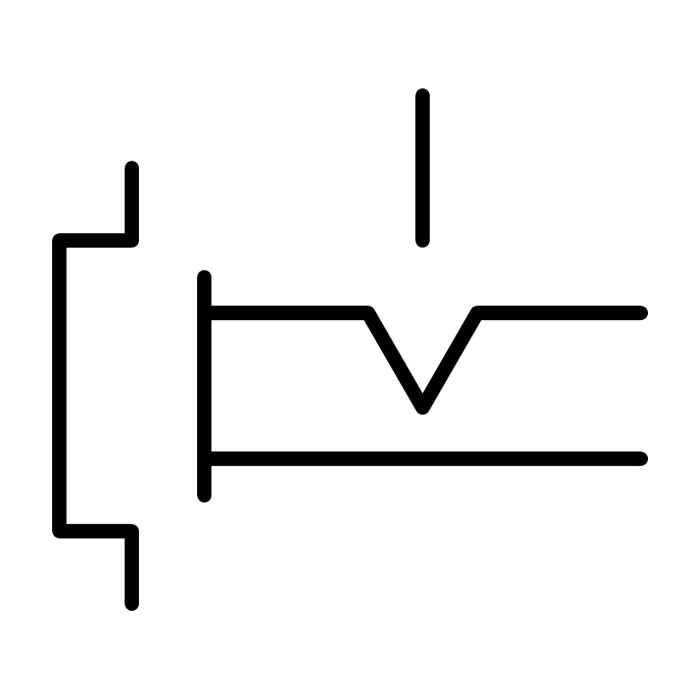
Single Acting Cylinder, Front Spring with Position Sensing
Single Acting Cylinder, Front Spring, Through-rod with Position Sensing
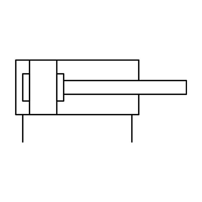
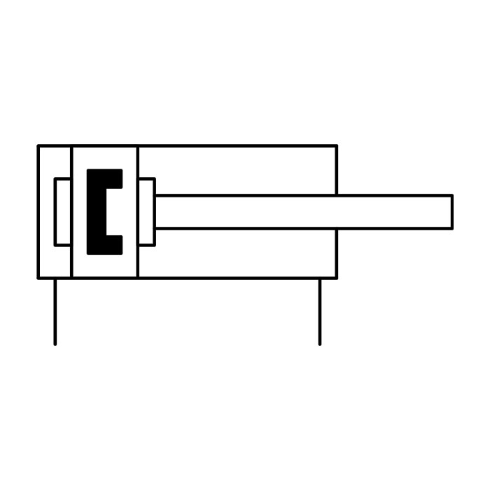
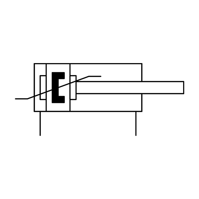
Double-acting cylinders use compressed air for extending and retracting the piston rod, by reversing the air flow direction. They can produce greater forces, and are used more commonly than single-acting cylinders. They can be used for both pushing and pulling.
Other types of Pneumatic Cylinder:
Double Acting Cylinder, Fixed Mechanical Cushioning
Double Acting Cylinder, Fixed Mechanical Cushioning with Position Sensing
Double Acting Cylinder, Adjustable Cushioning

Double Acting Cylinder, Adjustable Cushioning with Position Sensing
Double Acting Cylinder, Self-adjusting Cushioning with Position Sensing

Double Acting, Through-rod, Fixed Mechanical Cushioning
Double Acting, Through-rod, Fixed Mechanical Cushioning, Hollow Piston Rod
Double Acting, Through-rod, Fixed Mechanical Cushioning with Position Sensing

Double Acting, Through-rod, Adjustable Cushioning with Position Sensing
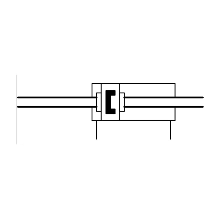
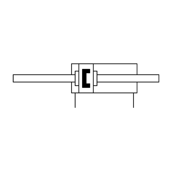
In this type of cylinder, the piston rod does not end its stroke at an end cap, but extends the stroke through both ends of the cylinder. This allows for the forces and speeds of the stroke to be equal on either side.
Single Acting Cylinder, Front Spring, Through-rod with Position Sensing
Single Acting Cylinder, Front Spring, Through-rod, Hollow Piston Rod with Position Sensing
Double Acting, Through-rod, Fixed Mechanical Cushioning
Double Acting, Through-rod, Fixed Mechanical Cushioning, Hollow Piston Rod
Double Acting, Through-rod, Fixed Mechanical Cushioning with Position Sensing
Double Acting, Through-rod, Adjustable Cushioning with Position Sensing
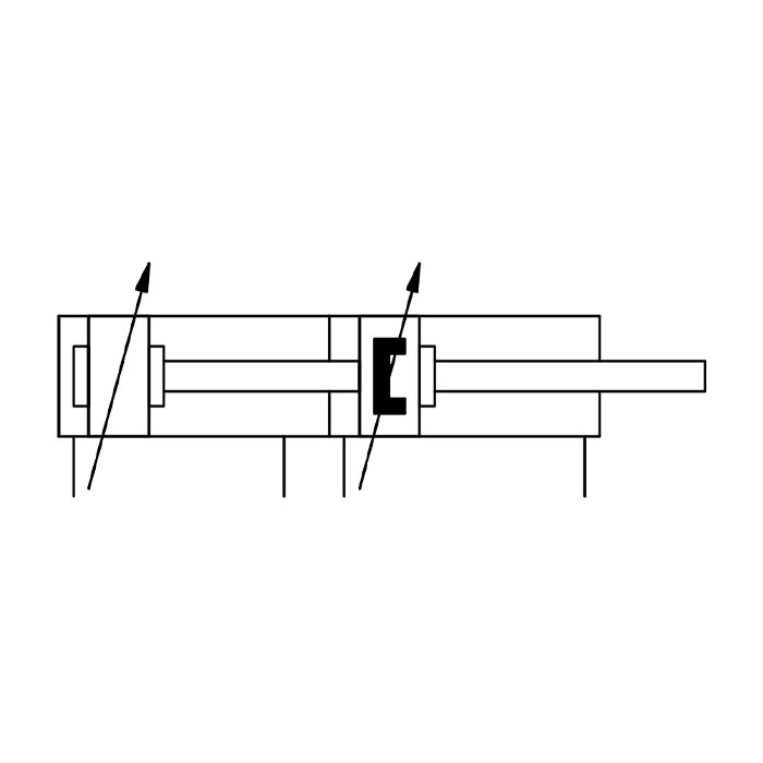
Tandem cylinders are a system whereby two or more pistons are connected via a common piston rod. This system is useful where only a small bore is possible or the supply pressure is low, and can generate a relatively high level of force.

Tandem Cylinder, Two Stage, Fixed Cushioning with Position Sensing
Tandem Cylinder, Two Stage, Adjustable Cushioning with Position Sensing
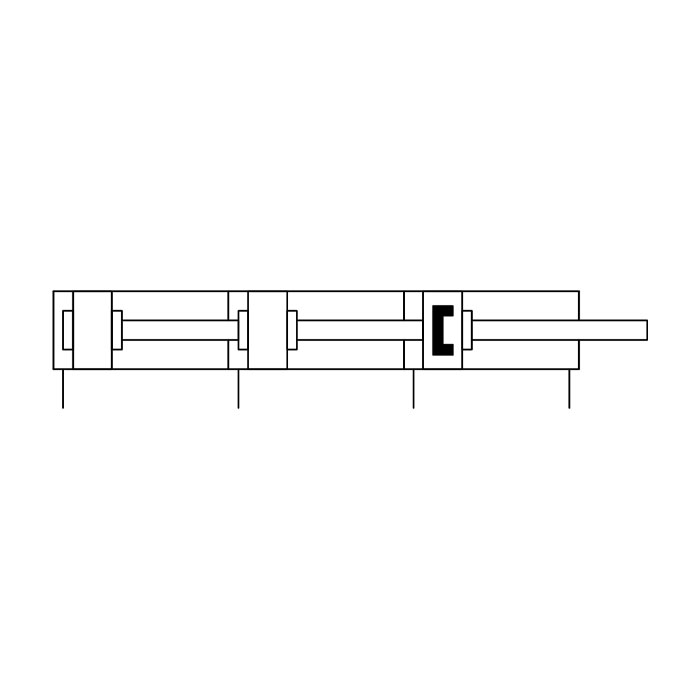
Tandem Cylinder, Three Stage, Fixed Cushioning with Position Sensing
These are cylinders that impart force by means of a mechanical slide or magnetic coupling, which is typically attached to a table or other component that travels along the cylinder body. The stroke does not extend beyond the body of the cylinder, but the cylinder length can be greater, and force is the same in both directions.
A cable cylinder still has an opening at one end, or both ends, but the piston rod is replaced by a flexible cable. A belt cylinder is open at only one end, with the belt passing round a motorised screw or toothed gear that keeps it turning. Cylinders using flexible cable or belts must be kept in tension.
Rodless Cylinder, Double Acting, Fixed Cushioning with Position Sensing
Rodless Cylinder, Double Acting, Adjustable Cushioning with Position Sensing
Rodless Cylinder, Double Acting, Self-adjusting Cushioning with Position Sensing
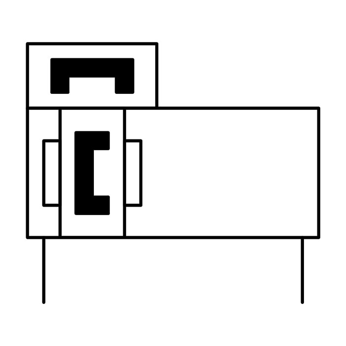
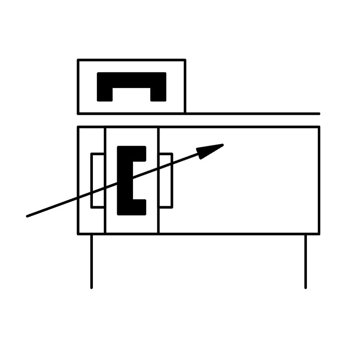
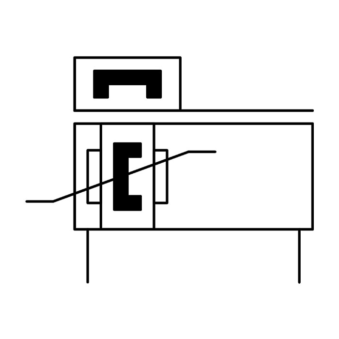
Pneumatic rotary cylinders are available in two main types: vane or swivel, and rack and pinion. In the latter type, a rack gear is attached to the cylinder piston. When actuated, their linear movement causes the pinion gear and output drive shaft to rotate. Vane cylinders operate in the same way as windmills: a lightweight (usually aluminium) vane is mounted inside the cylindrical chamber on a central shaft, and the air pressure makes it turn. Both types can be either single-acting or double-acting.
In a single-acting rotary cylinder, air pressure is applied to only one side of the centrally mounted vane, which forces it to rotate until the drive shaft has completed one stroke. In a double-acting rotary cylinder, once the drive shaft has completed one stroke, air pressure is then applied to the opposite side of the vane, forcing it to return in the opposite direction.
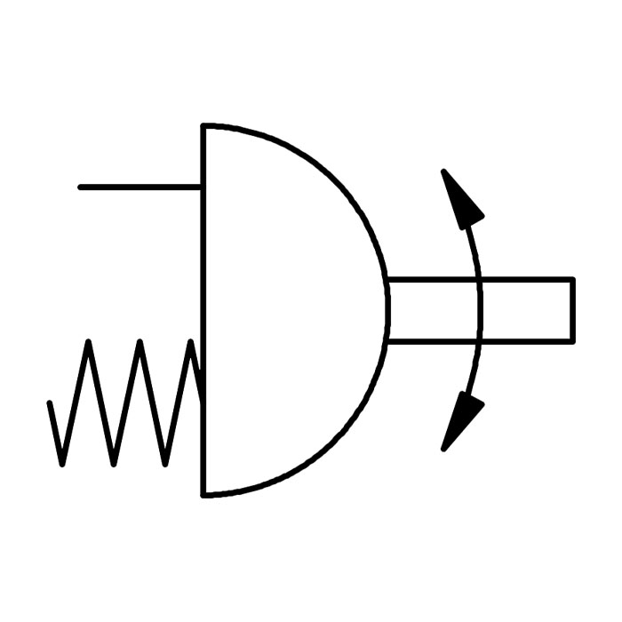
Single-Acting Rotary Cylinder
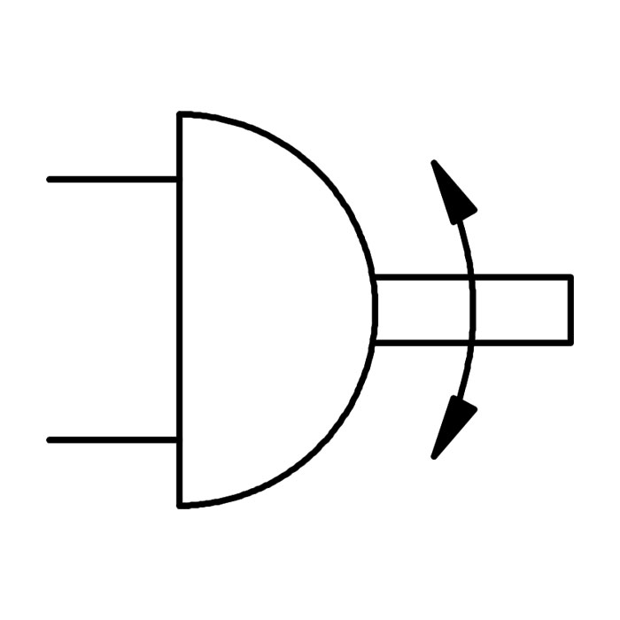
Double-Acting Rotary Cylinder
Rotary indexing tables are used in machining and a wide variety of other applications. Objects are mounted on a flat disc that rotates, using pneumatic power to start and stop the table at precisely measured angular intervals.
Rotary Indexing Table
As well as the cylinder body and piston rod, the pneumatic cylinder is constructed with metal end caps. The piston decelerates as it reaches the end of its stroke so as to reduce the impact of a metal piston on a metal end cap. Pneumatic cylinder cushioning is added to the assembly to reduce this impact further, cutting down on vibration or bouncing. Cushioning also reduces impact noise, which could, if excessive, constitute a health and safety hazard.
Cushions can be applied to the cylinder in a variety of configurations, including fixed mechanical options such as shock absorbers or bumpers. There is also a magnetic type, an option with adjustable cushioning at one or both ends, and a relatively new type of cushioning which is self-adjusting.
Fixed external cushioning is the most economical option. It is designed for limited speed and used on smaller, predetermined loads, so it cannot be changed if the conditions of use are altered. Bumpers or other mechanical cushioning incorporate some type of flexible material, such as an elastomer, into the end cap or part of the piston to reduce the impact.
Double Acting Cylinder, Fixed Mechanical Cushioning
Double Acting Cylinder, Fixed Mechanical Cushioning with Position Sensing
Double Acting, Through-rod, Fixed Mechanical Cushioning
Double Acting, Through-rod, Fixed Mechanical Cushioning with Position Sensing
Double Acting, Through-rod, Fixed Mechanical Cushioning, Hollow Piston Rod
Adjustable air cushioning works by limiting the volume of air that is normally released as the piston stroke terminates. Adjustable cushions have an external adjusting screw that permits varying types of load.
Double Acting Cylinder, Adjustable Cushioning
Double Acting Cylinder, Adjustable Cushioning with Position Sensing
Tandem Cylinder, Two Stage, Adjustable Cushioning with Position Sensing
Rodless Cylinder, Double Acting, Adjustable Cushioning with Position Sensing
Self adjusting cushioning has specially engineered longitudinal air channels on the inside of the cylinder. These allow exhaust air to be vented in a controlled manner, providing optimal damping. The system is designed to adapt its characteristics automatically when any changes occur in parameters such as pressure, friction or load.
Double Acting Cylinder, Self-adjusting Cushioning with Position Sensing
Rodless Cylinder, Double Acting, Self-adjusting Cushioning with Position Sensing
Rodless Cylinder, Double Acting, Self-adjusting Cushioning with Position Sensing
Sensors can be used on a pneumatic cylinder piston to identify its linear position during operation. Magnets are often already attached to the piston internally by the manufacturer, so proximity sensors can detect the extension and retraction of the piston. Sensors can also be mounted at any desired position along the cylinder body if more precise positioning is required. Installation of multiple sensors will provide multiple position feedback on one cylinder.
Double Acting Cylinder, Self-adjusting Cushioning with Position Sensing
Rodless Cylinder, Double Acting, Self-adjusting Cushioning with Position Sensing
Double Acting Cylinder, Adjustable Cushioning with Position Sensing
Double Acting, Through-rod, Adjustable Cushioning with Position Sensing
Tandem Cylinder, Two Stage, Adjustable Cushioning with Position Sensing
The following is a guide to the principal symbols found in a pneumatic air supply and distribution system. These are generally a combination of geometric shapes such as circles, squares, triangles and rectangles, together with directional arrows. These can be applied separately or in combination, and used in conjunction with solid or dotted lines, connecting dots at cross, elbow and T-junctions, and various electrical or electronic wiring symbols. As a general rule, circles are used for drive items such as motors, pumps and compressors, while squares and rectangles represent actuators, cylinders and valves.
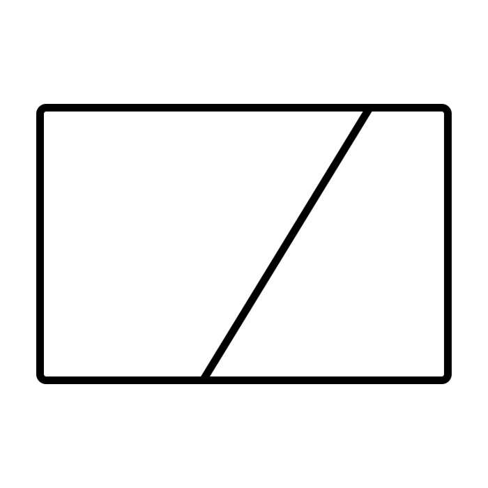
The symbol for a compressor is similar to the air motor symbol. The addition of a diagonal line arrow through the circle indicates variable displacement, as opposed to a fixed displacement compressor which would have no diagonal line arrow.
High-pressure air can be produced using piston, screw or vane compressors. All the variants in a particular component can be shown by the addition of extra lines or arrows to a basic simple shape.
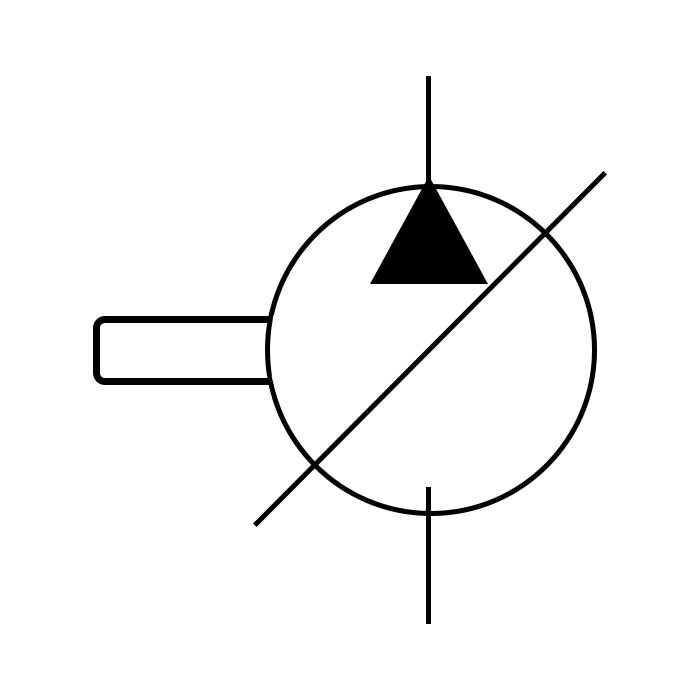
Compressor
Main air is what is supplied by the compressor and is shown by a circle with a dot at the centre and a connecting line from the circle.
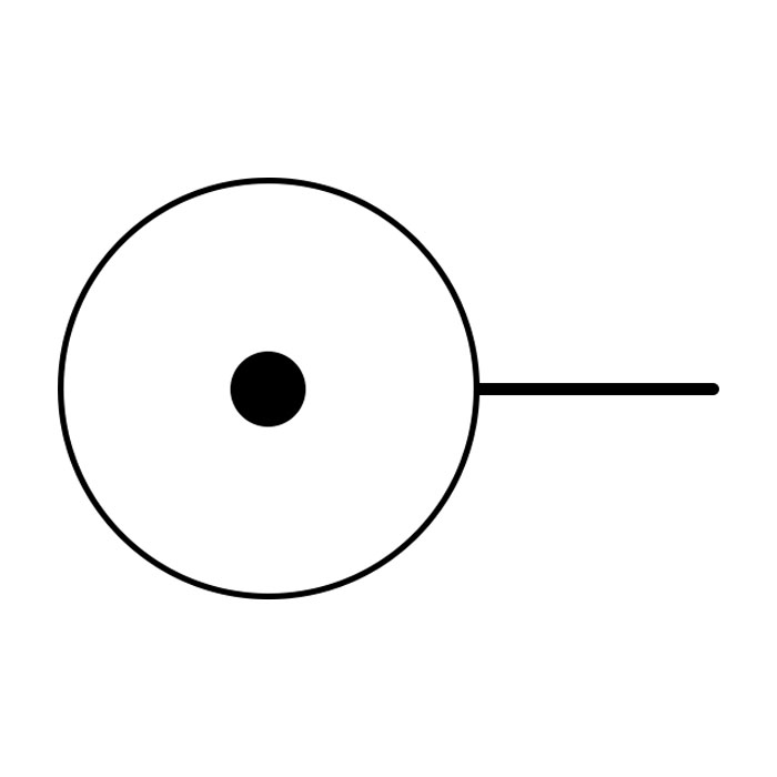
Main Air
The air produced by the compressor is stored in a vessel called the receiver or reservoir. The function of the receiver is to store the air for future use, to smooth out uneven pressure, and to allow water to fall out of the air to the bottom of the tank where it can be drained off. The symbol for the air receiver is almost recognisably a storage tank: a two-dimensional elongated cylinder. One or more solid lines leading into/out of the tank indicate its intake/output lines.
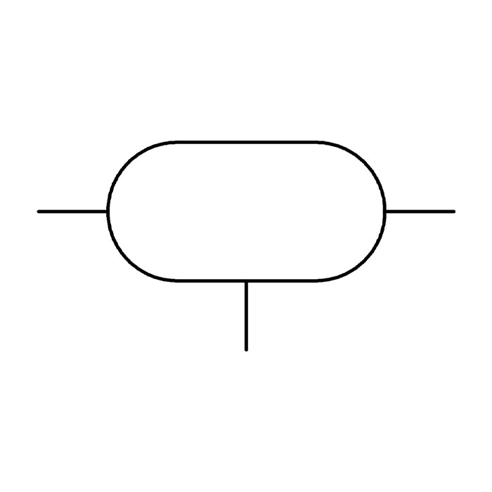
Reservoir
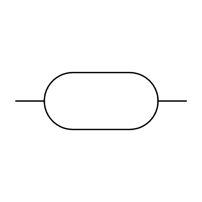
Reservoir
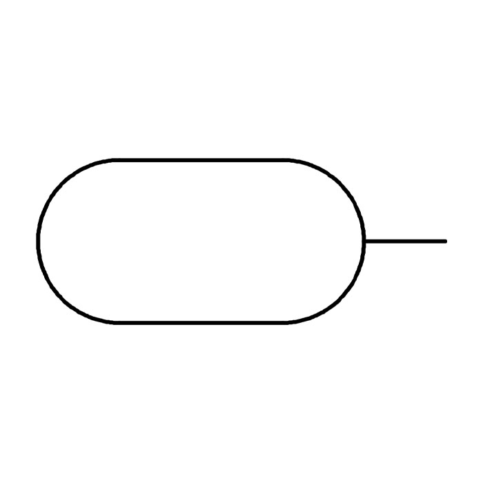
Reservoir
The compressed air distribution system is via connected lines or pipes to operating equipment, or via unconnected lines that cross over. Connected lines are depicted with a solid dot at line junctions, such as T-junctions, while crossed over lines can either have no dot, or a directional arrow at the cross-over point. Pneumatic pipes running in a factory are typically installed running downhill, to allow more excess water to run off.
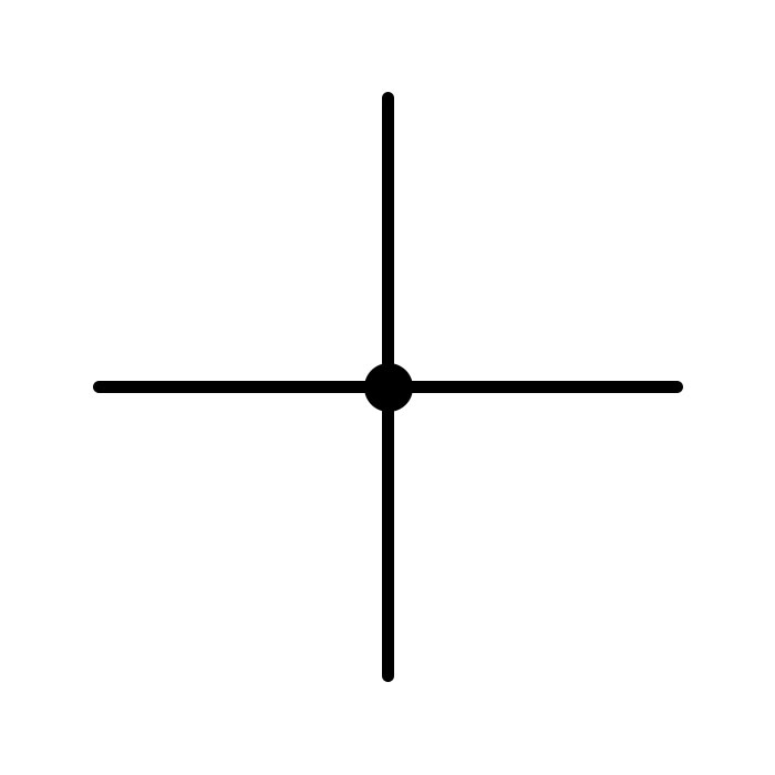
Air Pipes Connected/Not Connected
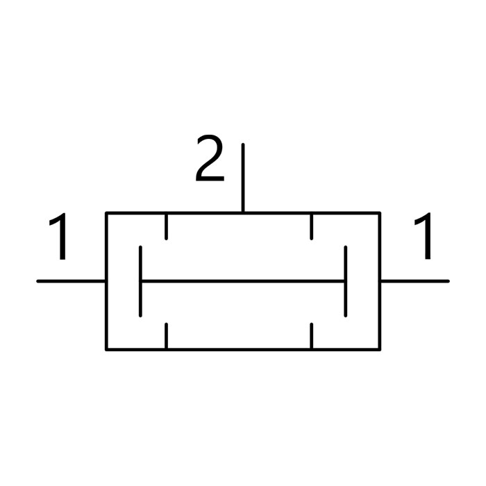
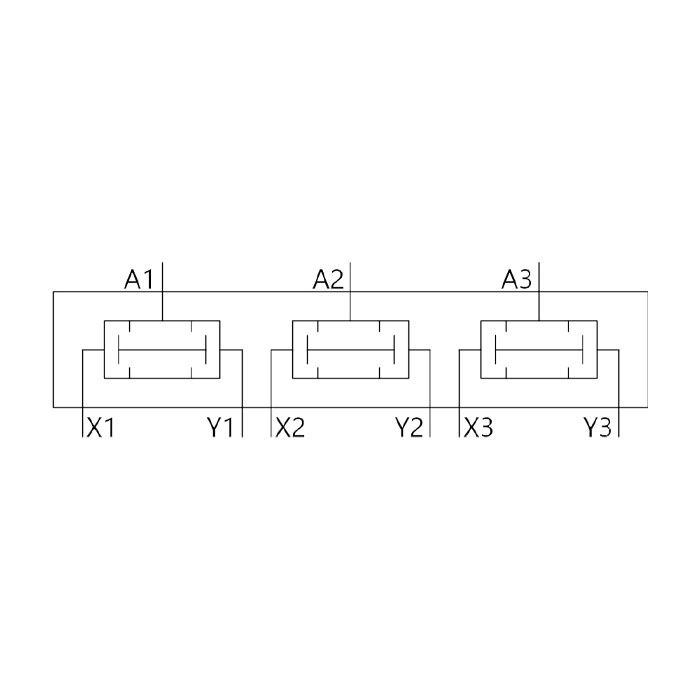
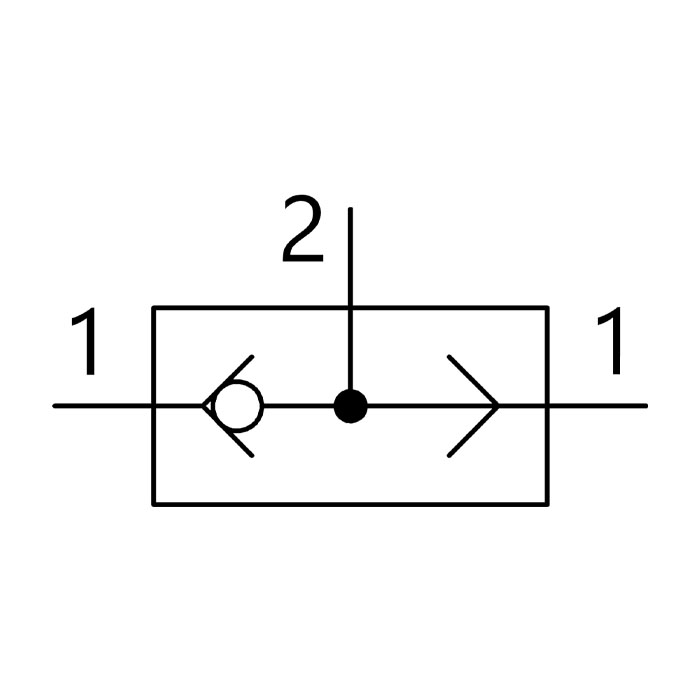
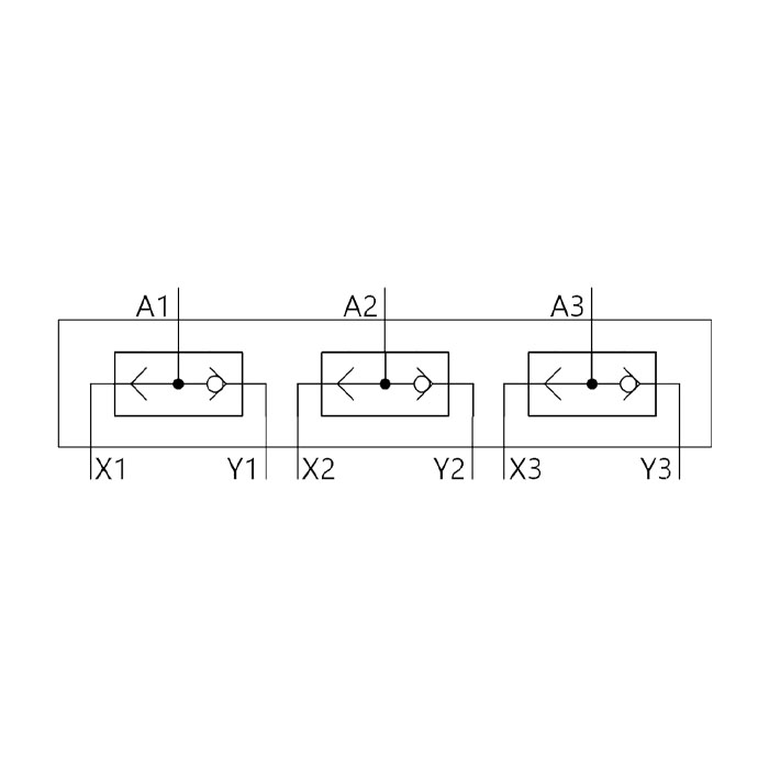
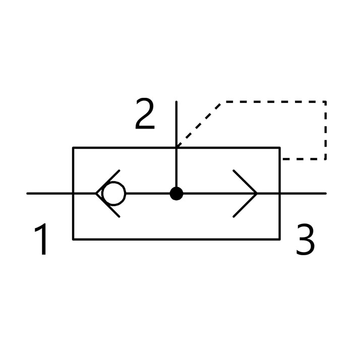
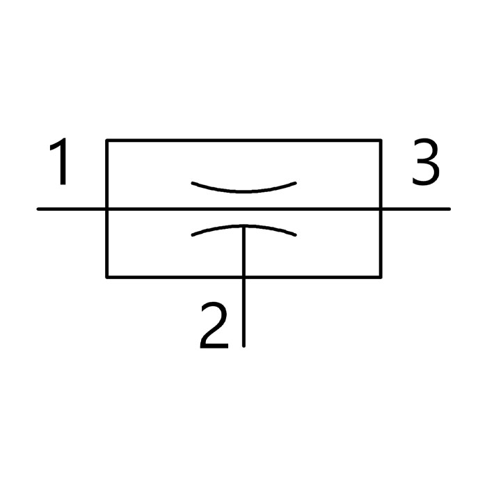
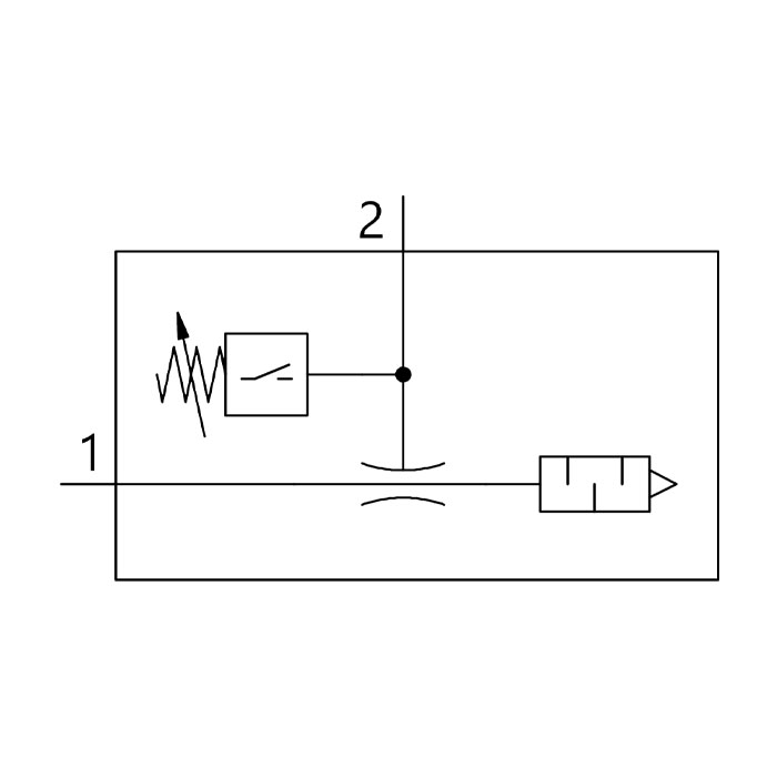
A manifold is used in engineering to define a pipe or closed space that has several openings or ports. This allows for the connection and switching of multiple components in any kind of circuit, including electrical and air treatment systems. In a diagram, the manifold is shown as a cross junction within a square, offering more than one connection.

Branching Module/Distributor
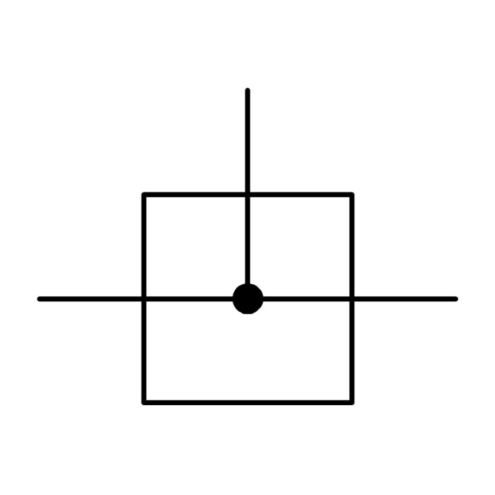
Branching Module/Distributor
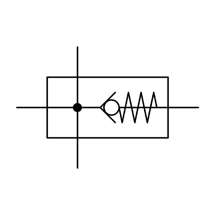
Branching Module/Distributor with Non-return

Branching Module/Distributor with Pressure Switch
While it is still possible to carry out filtration, regulation and lubrication separately, it’s more common, and more efficient, to use a combined FRL unit. For the purposes of identifying symbols, each of these components will be described individually.
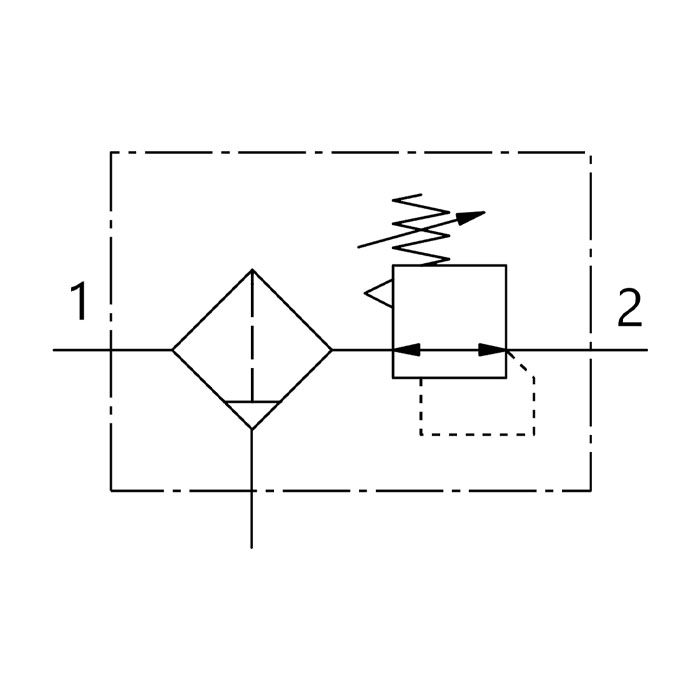
Filter Regulator, Manual Drain
Filter Regulator, Manual Drain
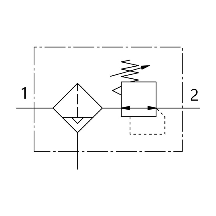
Filter Regulator, Automatic Drain
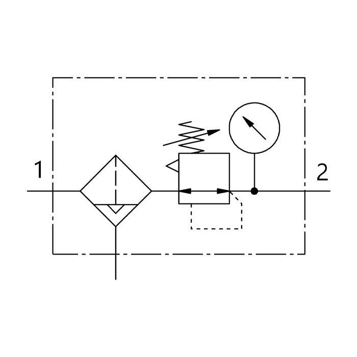
Filter Regulator, Automatic Drain, Pressure Gauge

Filter Regulator, Electrical Regulation, Automatic Drain
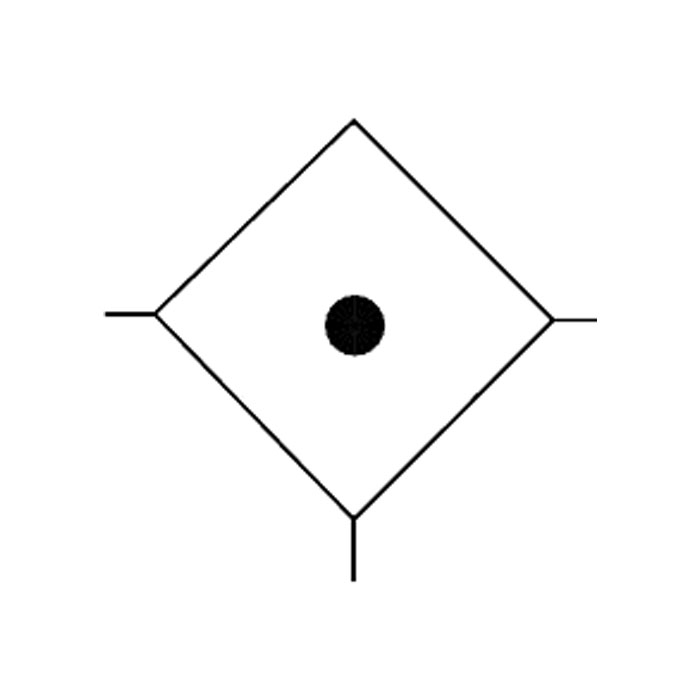
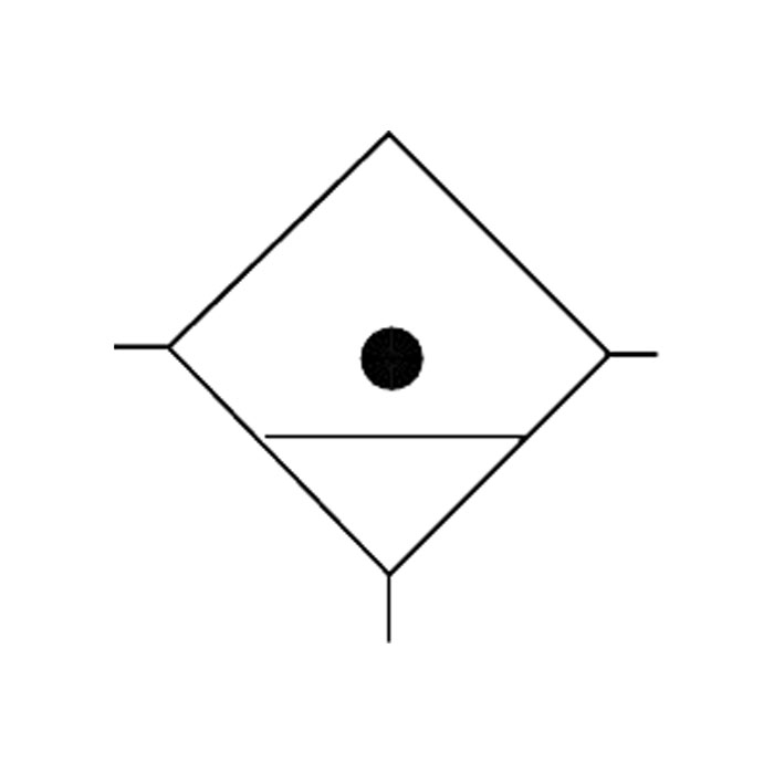
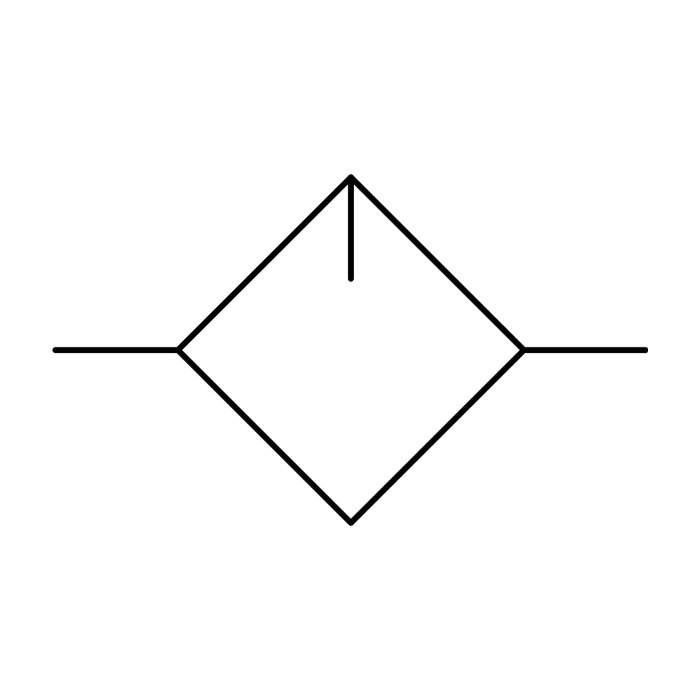
Compressed air filters remove moisture and contamination particles from the compressed air systems. If allowed to remain, these would block small ports and jam spools. Particles are retained or collected by a sintered filter. Depending upon the grade of filtration, particles of magnitude ranging between 40 and 5 ?m can be removed. Liquids and moisture are separated using centrifugal force. The condensate that accumulates in the filter bowl must then be emptied, otherwise the moisture will be pulled back into the compressed air by the drawn-in airflow.
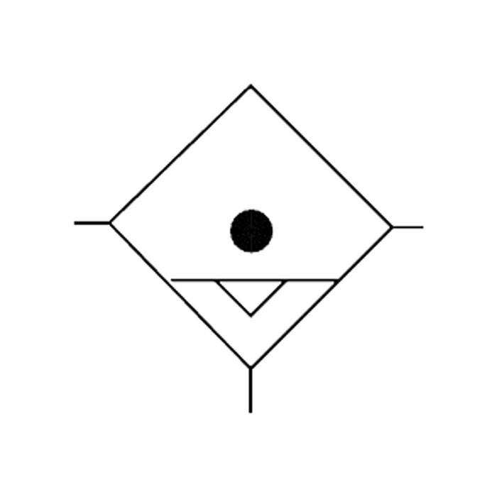
The diamond shape is commonly used for all air conditioning components. Various types of sintered filter are available, with variations of line and internal additions to indicate if drainage is used, and the type of drainage.
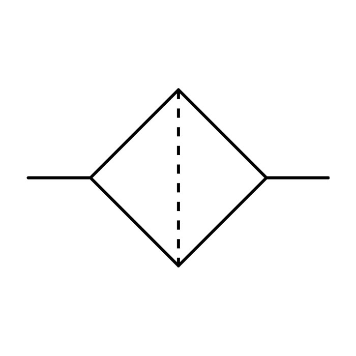
Filter Without Drain
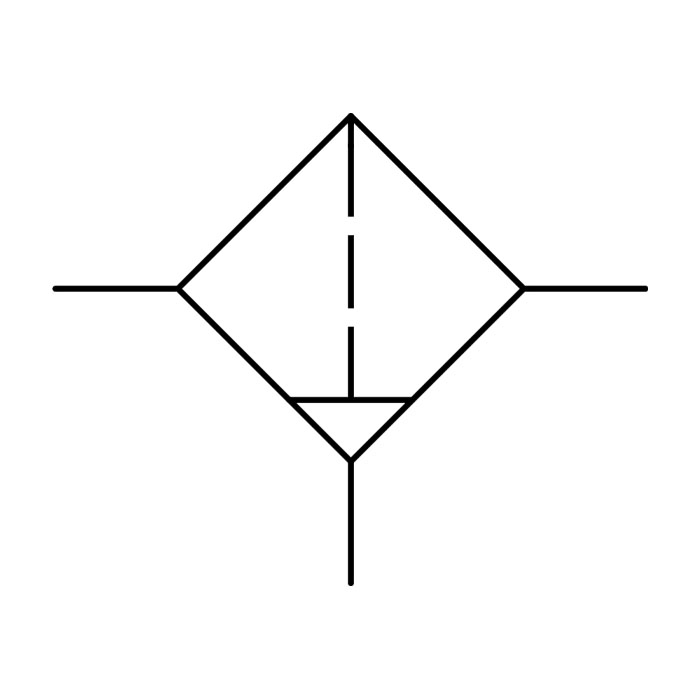
Filter With Manual Drain
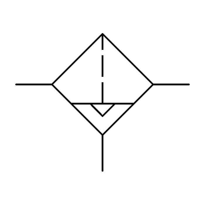
Filter With Automatic Drain
Vacuum Filter

Water Separator Automatic Drain
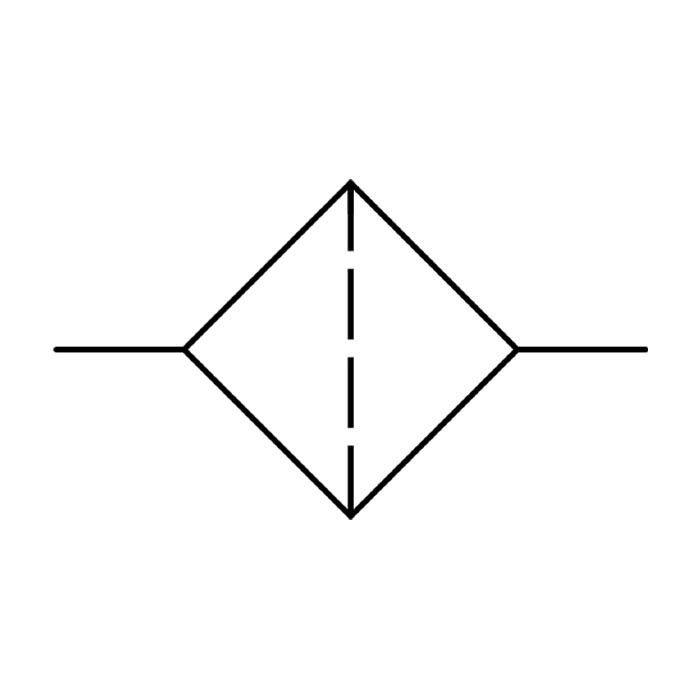
A coalescing filter works by using fibres in the filter element to attract minute moisture and oil particles. While coalescing filters are ideal for liquid filtration, they will also attract other particulates such as rust, which can reduce the life of the filter element.
Without Drain
With Manual Drain
With Automatic Drain
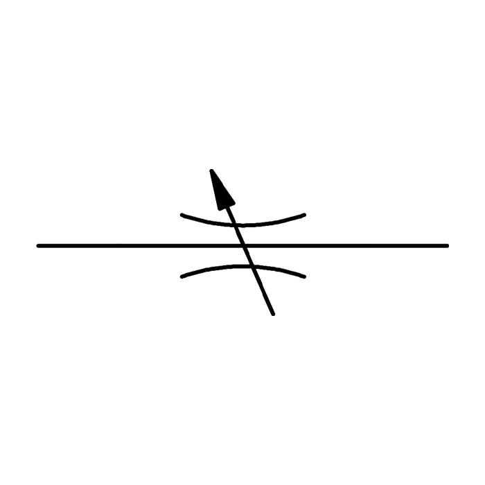
Input air supply from a compressor is usually at a higher pressure than is necessary to equalise any loss of pressure in the distribution system, so a regulator is used to reduce it. A pilot signal monitors the valve's output pressure to the connected devices and acts against a spring that sets the required pressure. Regulators are also differentiated by their type.
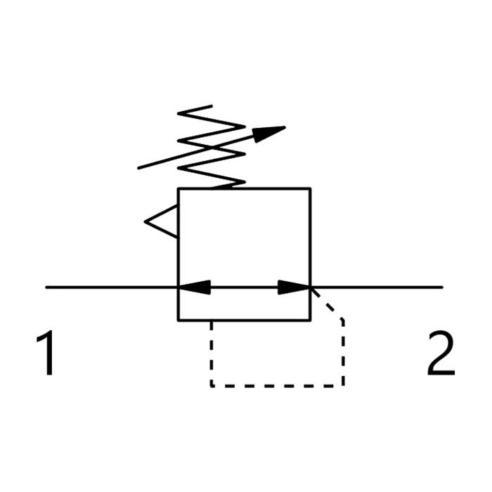
Regulator with Relieving
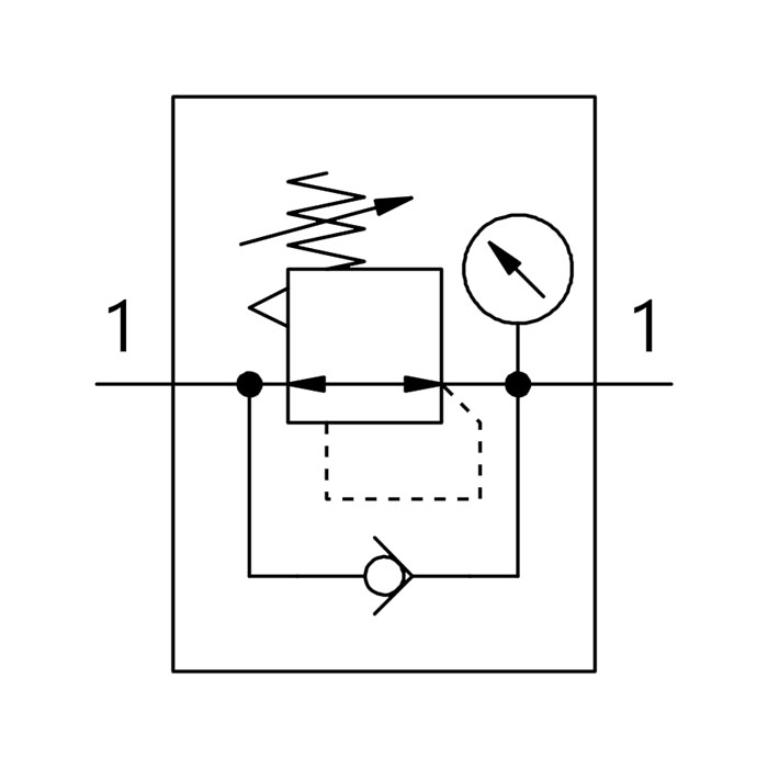
Regulator, Return Flow and Pressure Gauge
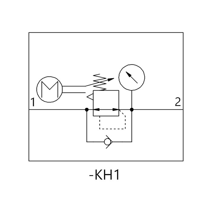
Electrical Pressure Regulator with Gauge
Precision Vacuum Regulator

Precision Clean Regulator
Once the compressed air has been filtered and regulated, it will have had oil and moisture removed. This clean air is, can sometimes be too dry and harsh for the moving parts of pneumatic tools or systems, so it has to be lubricated with an aerosolised suspension of ultramicroscopic oil particles. The lubricator symbol is very similar to that of a basic filter, as it is part of the air treatment family.
Lubricator
Symbols are used in pneumatic air supply and distribution to illustrate the function of valves and other necessary devices in the system, which are then connected together to form circuits. Valves are one of the most critical components in a pneumatic system, because they control and direct the air supply in the connected devices which carry out mechanical operations.
Directional air control valves are therefore the foundation of pneumatic control. The symbols that are used to represent these valves on a schematic or product label provide the user with detailed information which tells them how the valve works. This will normally include the actuation method (e.g. electric, pneumatic, manual, etc.), the flow paths, the number of possible valve positions and the number of its ports. Pneumatic valve symbols are always drawn in their un-actuated state.
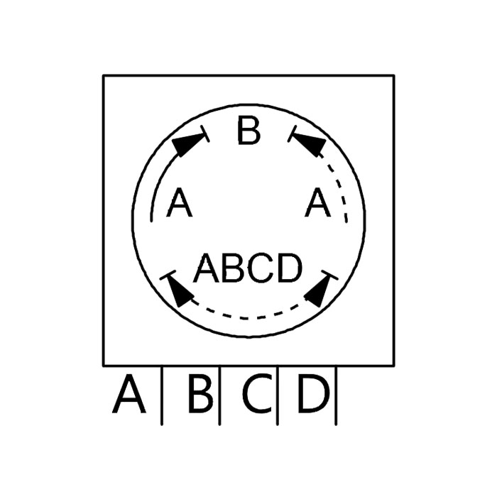
Most valve symbols show the number of ports, number of positions and type of actuation. On the sides of the valve symbol is usually the actuator which will make the valve change its position. The arrows illustrate the valve position and airflow direction. These represent the operating states and describe the way the valve functions.
Each box gives an indication of how many ports the valve has, so if each box shows two ports (top and bottom centre) then it is a 2-port valve. If there are only two boxes in the symbol this indicates a valve with only two positions, called a 2-stage valve.
So a valve with two ports in each of two boxes is a 2-port, 2-stage valve (2/2 Valve). This means that it can have two positions or operating states for each 2-port valve (Input and Output: Open or Closed).
In the top box, the directional arrow indicates that each of the two ports is blocked (Normally Closed, or NC), so that no air may pass through. In the bottom box, those two ports are both depicted as open (Normally Open, or NO), so that air may flow through the valve.
Ports are the valve openings where pipes or hoses can be connected. They have their own standard for numbering (designated under ISO 5599-3), with up to five ports stamped onto the valve casing. More ports can be designated for such additional circuits as signalling control and auxiliary pilot air.
Port 1 is for the input air supplied from a compressor or other similar device and distributed via a manifold.
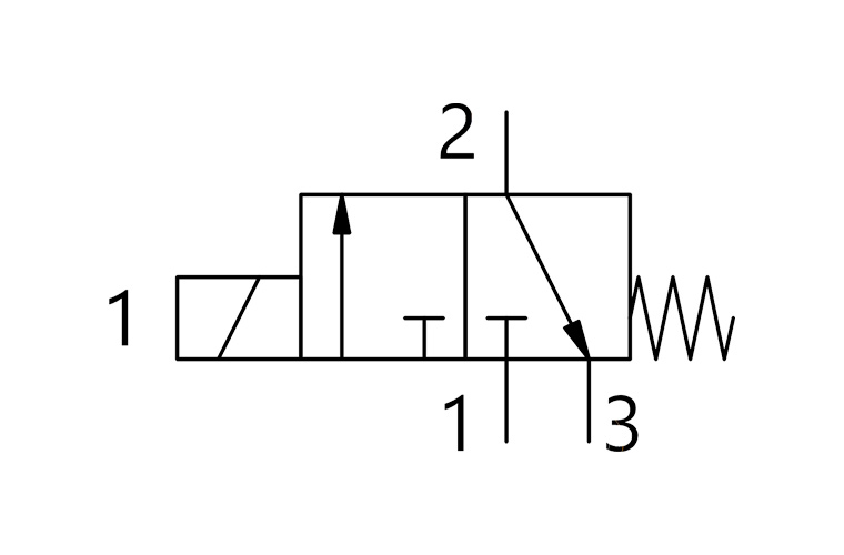
3/2 Valve
Port 2 is the output connection, where the working components are connected, usually cylinders. On a 5-port valve, commonly used with a Double-Acting Cylinder, the Port 2 output is usually connected to the in-stroke and Port 4 is usually connected to the out-stroke.
3/2 Valve
Exhaust is the waste or trapped compressed air that is vented from the circuit into the atmosphere after the actuation of the valve. On the 5-port valves used for Double-Acting Cylinders, the Port 3 Exhaust outlet is supplemented by a second Exhaust outlet at Port 5.
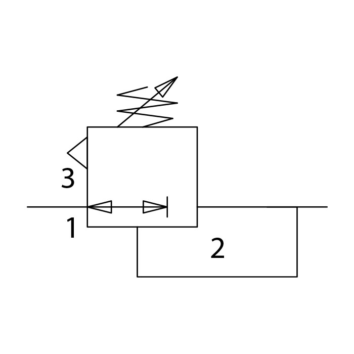
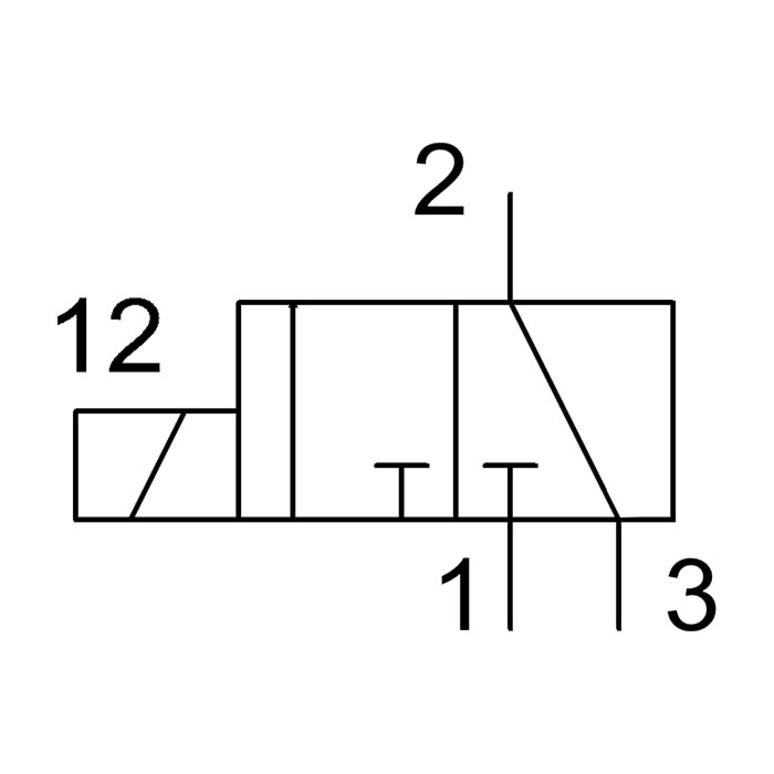
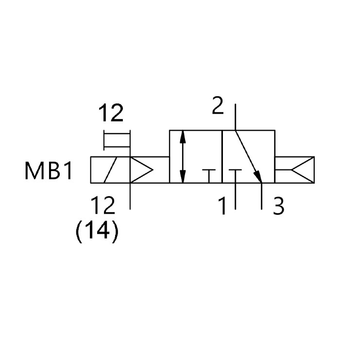
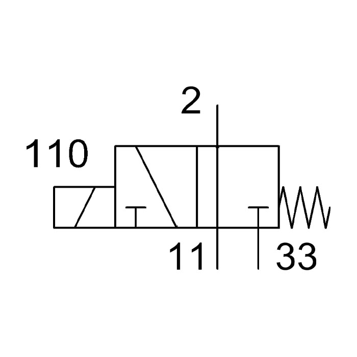
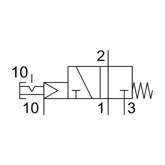
A 3-2 valve is commonly used for Single-Acting Cylinders. It has three ports and two states or positions. A 3/2 valve can be either normally open (NO) or normally closed.
3/2 Valve

3/2 Bistable Normally Closed, Lever
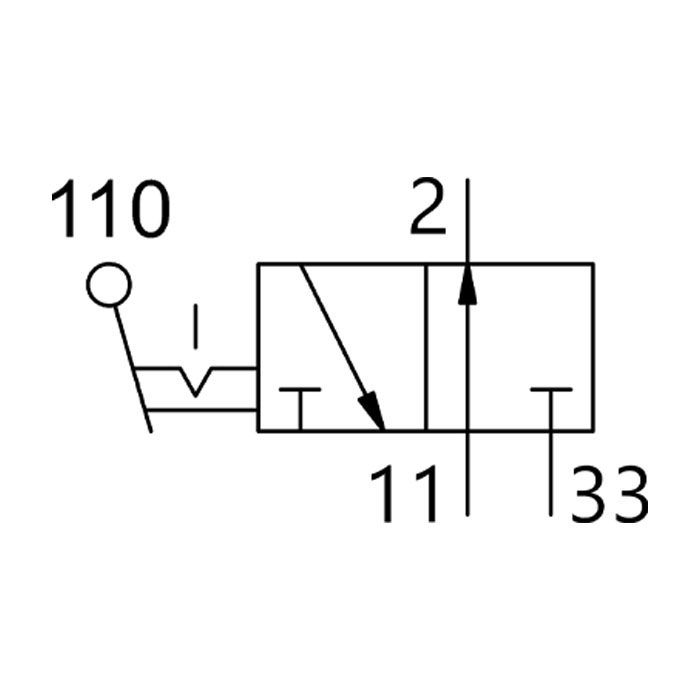
3/2 Bistable Normally Open, Lever
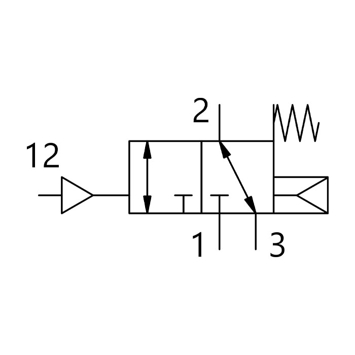
3/2 Bistable Normally Closed, Pneumatic, Spring Return
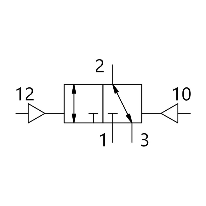
3/2 Bistable Normally Closed, Pneumatic
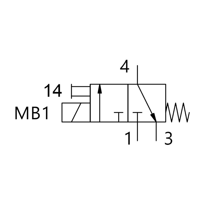
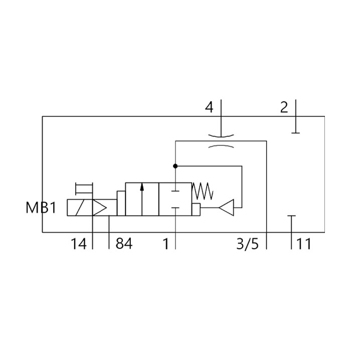
3/2 Bistable Normally Closed, Solenoid, Spring Return
3/2 Bistable Normally Closed, Solenoid, Monostable
The main air input to the valve is blocked, so the air in the valve is unable to reach the output connection to other components, e.g. cylinders. Any air remaining in the cylinder can be dispelled through the exhaust, allowing the cylinder to revert to its original position.

3/2 Valve Off State
The main air input flows freely through the valve, supplying output connections such as cylinders. A 3-port valve symbol depicts both states or positions side by side, generally in the Off (unactuated) state.
3/2 Valve On State
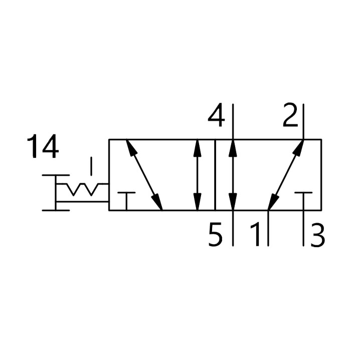
This valve has five ports drawn in each of two boxes, indicating that it has two stages of operation. 5-port 2-way valves have one Main Air, two Output Connections and two Exhaust ports and are commonly used for Double-Acting Cylinders. The 5/2 valve is operated by signals from a Pilot, using two 3-port valves which switch the spool in the 5-port valve from one side to another.
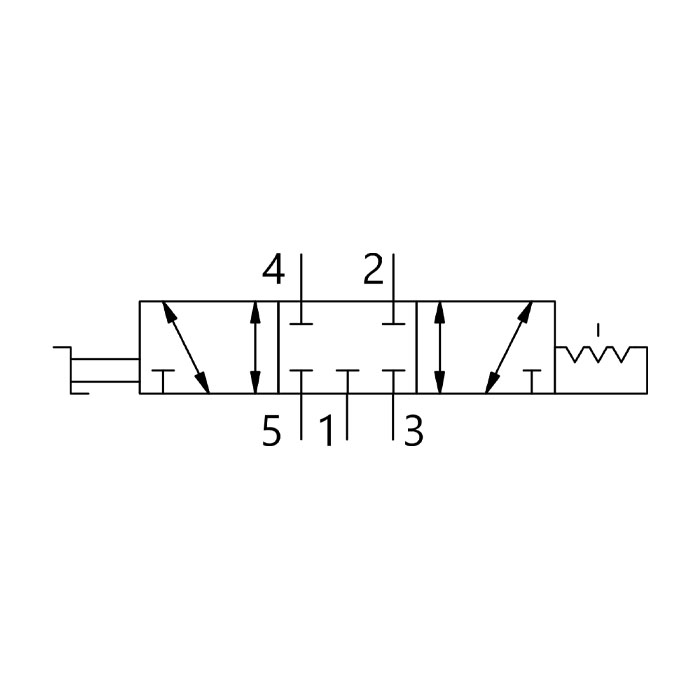
5/2 Bistable Manual Valve, Reversible, Detenting

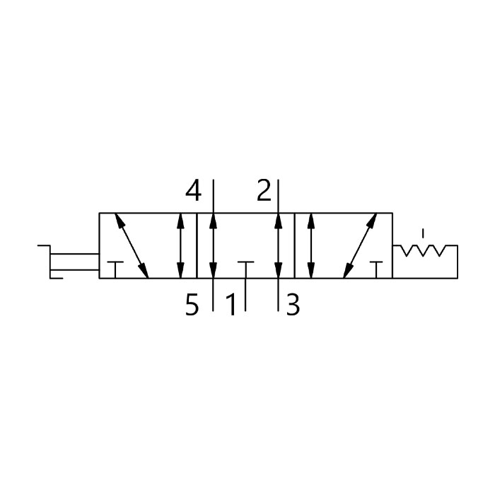
5/2 Monostable Manual Valve, Spring Return
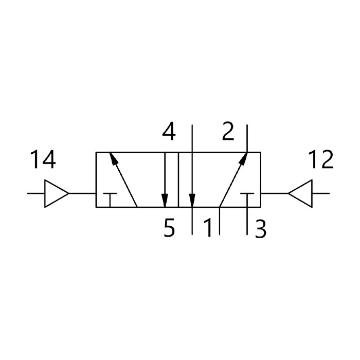
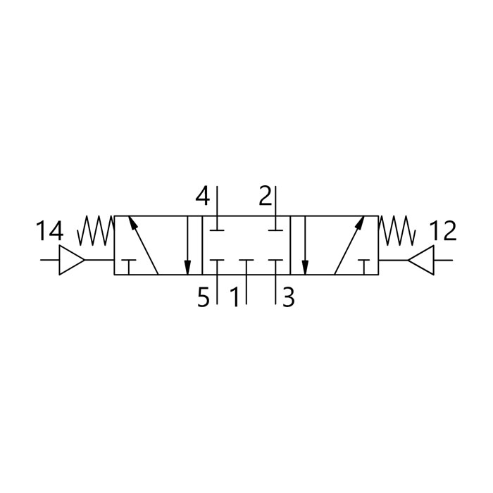
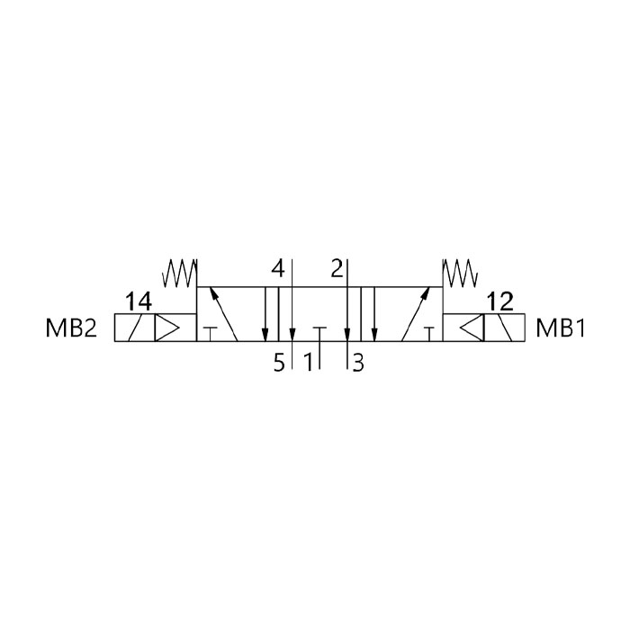
5/2 Bistable Pneumatic Valve
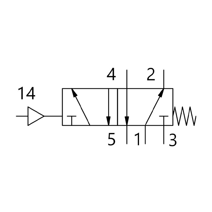
5/2 Monostable Pneumatic Valve, Spring Return
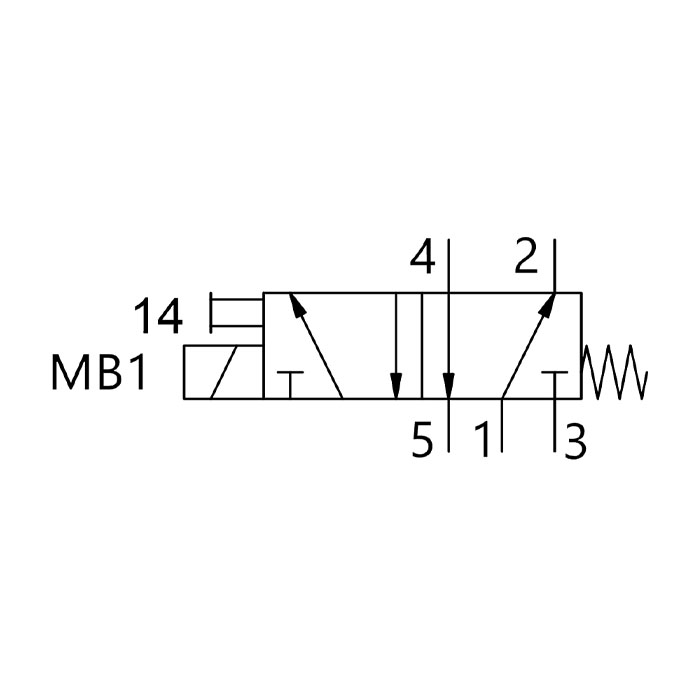
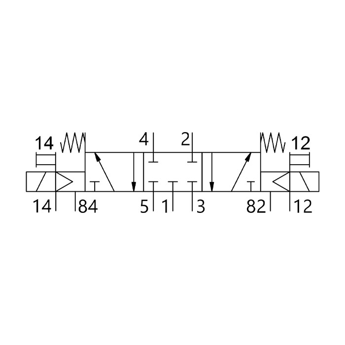
5/2 Monostable Solenoid Valve, Spring Return
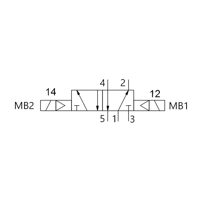
5/2 Bistable Solenoid Valve
This valve has five ports depicted in three boxes, indicating that it has three stages of operation. 5-port 3-way valves also have one Main Air, two Output Connections and two Exhaust ports, and are commonly used for Double-Acting Cylinders. The 5/3 valve is operated by signals from an actuator. 5-3 Valves can have the centre position either blocked, open to exhaust or pressurised.
5/3 Closed Centres, Manual, Detenting
5/3 Exhausted Centres, Manual, Detenting
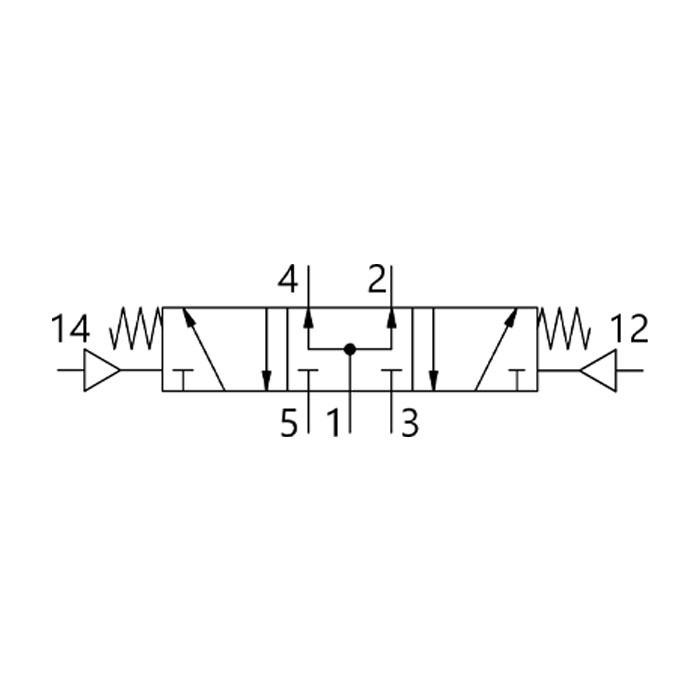
5/3 Pressurised Centres, Pneumatic, Mechanical Spring
5/3 Closed Centres, Pneumatic, Mechanical Spring
5/3 Closed Centres, Solenoid, Mechanical Spring
5/3 Exhausted Centres, Solenoid, Mechanical Spring
Control valves are primary valves that require switching in some form to pass on the control signal. They can be actuated in several ways, including pneumatically, manually, mechanically or electrically. Pilot and Solenoid Valves are switched indirectly from an external source, either another valve or an electric signal from a controller. These methods are increasingly common, but valves can still be actuated manually or mechanically, by means of push buttons, levers, rollers, toggles, etc.
A pilot actuator can operate a switch, or send signals to an actuator which will set its working pressure. The pilot monitors the valve's output pressure, and, for example, signals a regulator spring which can operate a spool in a 5-port valve.
Pilot Air
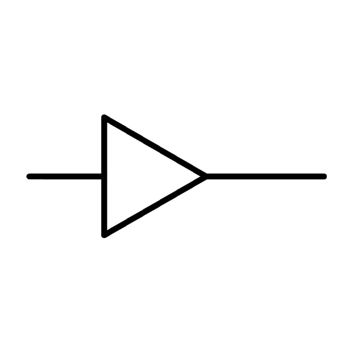
Solenoids change the operational state of a valve by means of an electrical pulse. Solenoid control combines pneumatics with electrical or, more recently, electronic governance systems, using a computer or PLC (programmable logic controller).
Solenoid
Pushbutton

Selector Switch
Key Switch
Mushroom Pushbutton
Mushroom with Detent
Toggle Switch
Toggle Switch with Detent

Roller Lever
Whisker Actuator
Key Switch
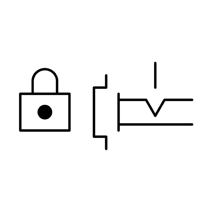
Lockable isolation valves have an isolation lock that will block the input airflow to the valve for greater safety when servicing pneumatic equipment. With the valve locked, all the downstream pressure will be vented, allowing work to be carried out safely. These valves are often positioned before the FRL unit.
Lockable Isolation Valve
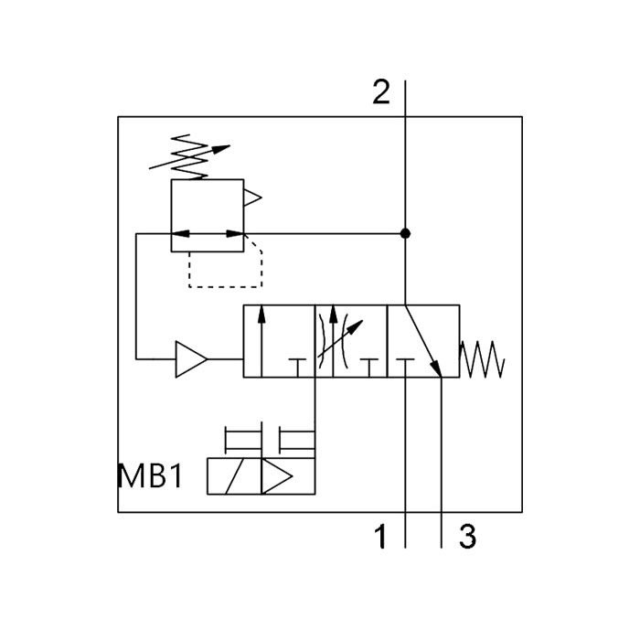
Soft start valves emulate a 3/2 manual valve function, which limits the amount of air input directly to the valve, allowing pressure to build up gradually and venting excess air from the exhaust port. Integral pressure sensors adjust the input supply according to the downstream pressure, allowing the soft-start valve only to open fully when the downstream pressure has reached a pre-set point. When that pressure is achieved, the valve is able to open all the way to allow the full amount of flow.

Pneumatic Soft Start Valve
Electrical Soft Start/Quick Exhaust Valve
Flow control valves are used to regulate the pressure or flow rate of the compressed air. Air flow can be regulated in one direction (unidirectional flow) or both directions (bi-directional), the means of control can be as simple as a manual actuator or a more complex electrical signal from a flow meter.
The purpose of reducing or increasing the airflow or pressure in a pneumatic circuit, to slow down or accelerate the pneumatic system, a common application is for speed control of a pneumatic cylinder.
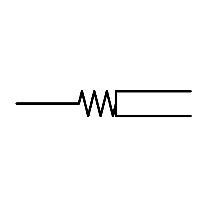
This symbol depicts a non-return or check valve, which restricts the compressed air supply so that it can only flow in one direction. Airflow in the other direction is blocked. This symbol can also be shown with a zig-zag line to denote a spring-loaded check valve.
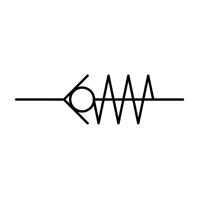
Non-return Valve
Non-return Valve

Unidirectional Blocking Valve
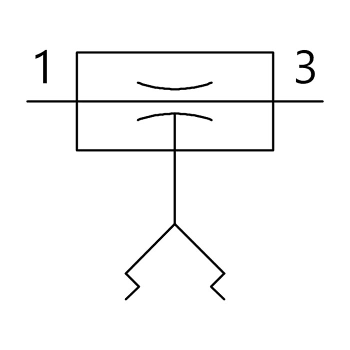
Unidirectional flow control valves are used to limit the speed of the cylinder's operation by controlling the flow direction of compressed air. The symbol incorporates a non-return or check valve. This restricts the air supply so that the air is restricted in one direction, and free-flowing in the other direction.
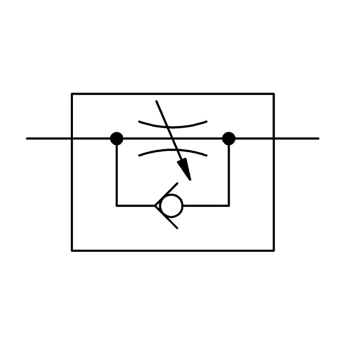
Unidirectional Flow Control

Silenced Exhaust Controller
The bidirectional flow control valve symbol is the same as the unidirectional one, but without the check valve. This indicates that the air is unrestricted and able to flow freely in either direction.
Bidirectional Flow Control
The symbol for a fixed value flow control valve has neither a check valve nor a variable arrow, indicating that the air may flow in either direction when the pressure is reduced to a fixed value.
'Logic' in electronics denotes the system of arrangement or 'gates' in circuitry that controls the way and order in which they operate. Similarly, 'air logic' or pneumatic logic is used to control the flow of air in a pneumatic system, by means of air logic valves. Pneumatic logic circuitry is much safer to use in hazardous environments where there might be, for example, a high level of moisture or dust.
Pneumatic logic systems are analogous to traditional logic gates. Valve gates such as OR, NOR, AND and NAND are almost identical in their function to similar electronic circuits, although they are somewhat different in form. In general terms, they equate to 3- or 4-way valves that include inlet port(s), control logic, outlet port(s), and exhaust vents.
An AND valve has two input signals which it must receive simultaneously in order to permit an output signal, i.e. both Input 1 AND Input 1(3) must be present for Output 2 to function. AND valves can be connected together in a series, with the output of the first unit forming one of the inputs on a second AND valve. This combines with a third signal on the second unit, meaning that three separate inputs must occur simultaneously before any output action can take place.
There also exist valves which are the opposite of this, called NOT-AND, or NAND valves. In this type of valve, the airflow will only pass through it to the Output if neither Input source port is actuated. If both input ports are actuated, this will make the Output port close.
"AND" Valve
"AND" Block
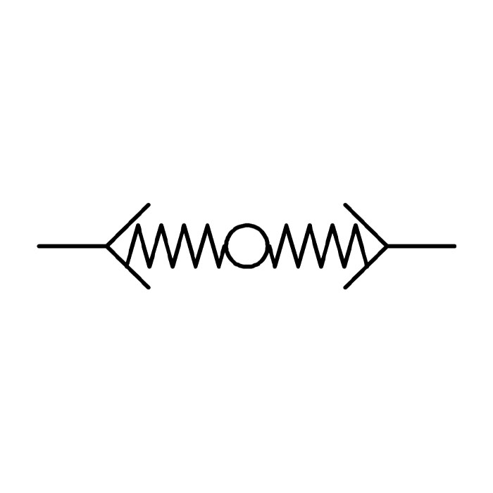
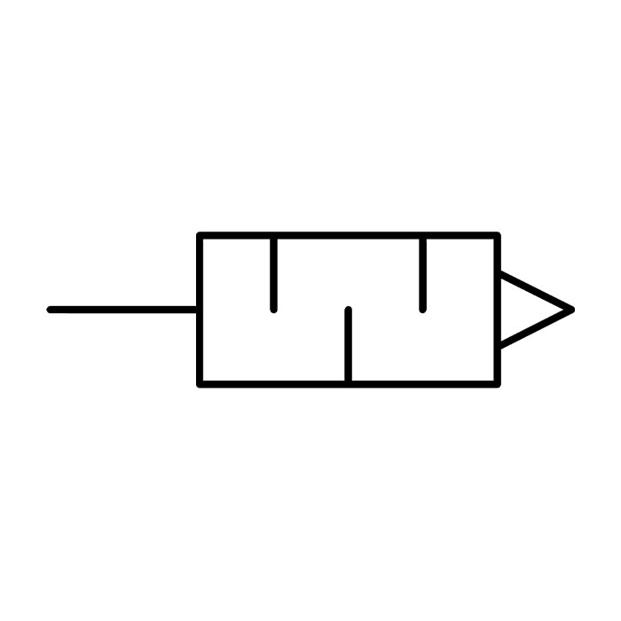
A shuttle valve allows the airflow to pass through it from either or both of two Input sources. The higher of the two inlet pressures forces a small ball or blocking element inside the valve from that end to the other, blocking it off, but leaving a central port open for the air to flow through.
In pneumatic logic, there are also NOT-OR or NOR valves which, like the NAND valve type, do exactly the opposite of 'OR' valves. In this valve, the airflow will only pass through the Output port if neither Input port is actuated, and the Output will close if either port is supplied.
"OR" Valve
"OR" Block
Quick Exhaust Valve
While a typical pneumatic system works by pushing objects away from the air source, pneumatic vacuum systems work by pulling objects towards it. It is a preferred choice for directing material to a single location, rather than multiple destinations, and enables the lifting of objects. No heat is applied to objects in a pneumatic vacuum system, and they also suffer fewer issues with leakage.
This set of symbols pertains to various components of a pneumatically driven vacuum system.
Vacuum Generator
Vacuum Generator

Vacuum Generator with Silencer
Vacuum Generator with Silencer
Vacuum Generator with Vacuum Switch and Silencer
Vacuum Generator with Electrical On/Off
Vacuum Generator with Bellows Suction Cup
Vacuum Suction Cup
Vacuum Filter
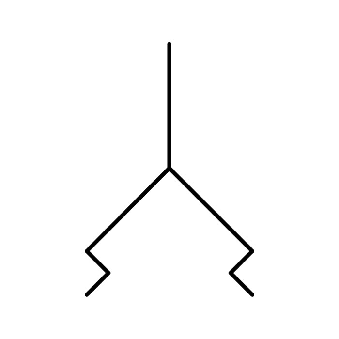
Air compression systems can make a lot of noise, particularly when they're venting exhaust air. A silencer is often added to reduce overall operational noise.
Silencer
Silencer Open
Silenced Exhaust Controller