How To Choose The Correct Pneumatic Fittings
Post By: Ryan King On: 23-09-2019 Read Time: 10 minutes - Guides - Pneumatics
Post By: Ryan King On: 23-09-2019 Read Time: 10 minutes - Guides - Pneumatics
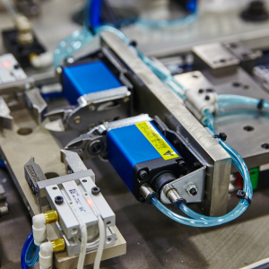
Pneumatic fittings are required in any kind of pressurised gas system to link together sections of tubing, pipe or hose. They typically have tighter seals and are subject to lower pressure than hydraulic fittings, and are frequently found in pneumatic instrumentation and logic control systems, as well as moving parts such as cylinders.
Although fittings may represent the minutiae of the overall pneumatic system design, they are perhaps the most important of all the elements. Pneumatic fittings, together with their pipes, hoses and tubes, connect all the other major components together, and can therefore have a major influence on the efficiency, safety and energy consumption of the entire system.
Pneumatics are used in many of today's industrial and automation environments, and there is an increasingly wide range of options from which to choose your components. Knowing how to choose pneumatic fittings is therefore all about suiting the materials to the job and its environment. In order to break down this process, you first need to identify:
The design of pneumatic fittings should allow the free flow of required air or gas without any opportunity for significant drops in pressure. Pipes and hoses should be configured as simply as possible, so that no energy is lost in the air's passage through the system. Always use straight runs wherever possible, and only use elbows and Ts if absolutely necessary.
When choosing your pneumatic fittings, there are some key environmental factors that must also be taken into account.
The operating temperature specified by the manufacturer defines the range of temperatures or the operational temperature ratings within which the particular fitting is designed to work. This is measured in degrees Celsius (°C) or degrees Fahrenheit (°F), and the fitting may well fail if it is made to operate above or below this specified range. It must be borne in mind that the ambient temperature of the inlet air to the compression unit will affect the compressed air output.
As air heats up or rises the pressure drops, so industrial automation equipment should generally only be used in a controlled temperature environment. In general terms, every 5º F of temperature reduction produces a 1% improvement in efficiency and power conservation, but both high ambient air temperature and low intake pressures will significantly affect performance. It's also a fact that an increase in operating temperature will cause a reduction in the operating pressure of polyurethane and nylon tubing.
The most common air contaminants are water, oil and particulates, such as dirt, rust and metal shavings. Such contaminants in the air intake are commonly removed by the filtration system, usually comprising a filter-regulator-lubricator unit (FRL). The lubricant also acts as a coolant in some types of compressor, but there is sometimes a danger of the heated lubricant getting back into the inlet air and causing contamination there. Additional contaminants in the form of bacteria or microorganisms can also be critical in some types of application, such as pharmaceuticals or food.
It seems simple, but it is essential to ensure that there is sufficient space around the installation to allow the best configured construction, as well as access for maintenance and repairs. It should be large enough to allow pipework to run naturally, and to permit a free flow of ambient air so the space doesn't overheat externally. The equipment also needs to be stable with no possibility of vibration.
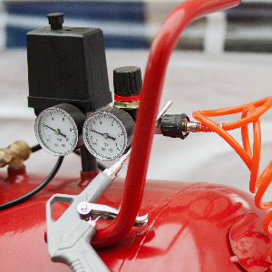
Pneumatic fittings are frequently rated for certain operational pressure ranges, based on the specifications of the equipment and what it is designed to do. This pressure range (in PSI, or pounds per square inch) is the one at which a pneumatic system will generally be running at its optimum level of performance. If the correct operating pressure is not maintained, it could cause the whole system to fail, and components are likely to leak, break or lose their pressurised seal.
In general terms, your system performance will suffer if it is operating at a pressure that is either above or below its specified operating range. If above, it can lead to system failure through bursts and leaks. If below, it is likely that the system won't function at all, since it has insufficient input energy.
In some application use cases, you may need to install a fitting which conforms to an industry or safety standard. The British Compressed Air Society (BCAS), for example, has a best practice guideline offering useful guidance on compressed air equipment for the food and beverage industry, including its selection, installation and maintenance. In these environments, the requirements for air purity are very strict, and may not allow for the use of compressors using oil-based lubricants. Bacteria and microorganisms are also a source of major concern.
While the BCAS guidelines are based on the British Retail Consortium's global food safety standards (ISO 22000 / ISO TS 22002-1) there are also specific standards which relate to the provision of compressed air. Design standards are also applied to many products by the German Technical Control Board (TUV)
The Health and Safety Executive (HSE) publishes a comprehensive list of applicable safety standards for use of compressed air, including both BS, EN and ISO standards. These standards govern all aspects of compressed air installation, from thermometers and pressure gauges to pipe supports, pipework and hoses. It is important for the safety of your personnel, and the optimal performance of your equipment, that you comply with all relevant standards.
When deciding how to choose the correct pneumatic fittings for your application, you should examine the different materials that are commonly used in order to determine their different physical properties, gas compatibility, and reaction to, for example, temperature changes.
Aluminium fittings are commonly used for low pressure, low density applications where its low tensile strength is not an issue. It is a lightweight material and most often chosen for its resistance to corrosion, but can be alloyed with other metals to increase its strength and density.
Brass is also corrosion resistant, but much stronger and more durable, and it offers good conductivity and high temperature ductility. It is most commonly chosen for pneumatic fittings because of its excellent performance and machinability.
Although typically more expensive, stainless steel already has excellent corrosion and chemical resistance, with the durability and strength of ordinary steel.
Polypropylene is a thermoplastic that is widely used for pneumatic fittings, as it has high durability, low price and wide compatibility with other materials. It demonstrates excellent bi-axial strength, cold flow and yield elongation. It can safely be used for applications in exposed areas, because it is resistant to weathering, ozone and UV radiation.
Composites are fittings made from various material combinations, such as carbon, graphite and fibreglass. These materials are also used in applications requiring high chemical resistance and temperature durability; they have a high melting point as well as low thermal and electrical conductivity.
For specialised environments, enhanced fittings can be engineered with additional protections such as integral lining, surface coating or plating, or special insulation.
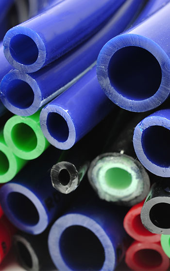
When deciding how to choose your pneumatic fittings, you need also to determine what type and size of tubing or hose you will need, whether it is measured in metric or imperial sizes, and whether it's made of metal or thermoplastic. And in the first instance, you need to differentiate between tube, pipe or hose.
Tubing and hose may seem to be the same, but tubes are designated by their external diameter so as to be compatible with push-to-connect fittings. Hose is designated by its internal diameter, and usually comes with rigid, swivel or quick-disconnect fittings that are attached at both ends. Pipes are entirely rigid, constructed from a single solid material and usually defined by their internal diameter dimension.
Tubes are relatively rigid vessels generally made from one solid material, typically some kind of thermoplastic, which can also be internally reinforced for higher strength:
Hoses are completely flexible vessels constructed from a variety of the same thermoplastic materials. An inner tube is reinforced with one or more layers of spiral-wound or braided fibres, with a protective outer cover. Hose is generally more expensive than tubing but is more rugged and durable, as it is often used for manual tools and gets dragged across abrasive surfaces.
Thread size is governed by standards, including BSP (British Standard Pipe) and NPT (National Pipe Thread), although there are many other international standards, and sometimes it depends on the industry and/or country of use. Thread size is always measured and formulated on the interior diameter of the conduit and corresponds to a specific number of threads per inch (TPI). The conduit size is measured in metric (mm) or imperial (inches), and proper sizing is critical, as over- or under-sized fittings will either be wholly incompatible or make an inadequate connection or seal.
The table below shows nominal thread sizes with corresponding values.
| BSPT & BSPP SIZE & PITCH |
DASH SIZE | BSPT MALE THREAD OD |
BSPP MALE THREAD OD |
BSPT FEMALE THREAD ID |
BSPP FEMALE THREAD ID |
||||
|---|---|---|---|---|---|---|---|---|---|
| inch – TPI | mm | inch | mm | inch | mm | inch | mm | inch | |
| 1/8 – 28 | -02 | 9,5 | 0.37 | 9,6 | 0.38 | 8,4 | 0.33 | 8,6 | 0.34 |
| 1/4 – 19 | -04 | 12,8 | 0.50 | 13,0 | 0.51 | 11,2 | 0.44 | 11,9 | 0.47 |
| 3/8 – 19 | -06 | 16,3 | 0.64 | 16,5 | 0.65 | 14,7 | 0.59 | 15,2 | 0.60 |
| 1/2 – 14 | -08 | 20,4 | 0.80 | 20,8 | 0.82 | 18,3 | 0.72 | 19,1 | 0.75 |
| 5/8 – 14 | -10 | 22,5 | 0.89 | 22,8 | 0.90 | 20,6 | 0.81 | 20,8 | 0.82 |
| 3/4 – 14 | -12 | 25,9 | 1.02 | 26,3 | 1.04 | 23,9 | 0.94 | 24,6 | 0.97 |
| 1 – 11 | -16 | 32,6 | 1.28 | 33,1 | 1.30 | 29,7 | 1.17 | 30,7 | 1.21 |
| 1.1/4 – 11 | -20 | 41,1 | 1.62 | 41,8 | 1.64 | 38,6 | 1.52 | 39,4 | 1.55 |
| 1.1/2 – 11 | -24 | 47,0 | 1.85 | 47,7 | 1.88 | 44,5 | 1.75 | 45,5 | 1.79 |
| 2 -11 | -32 | 58,6 | 2.31 | 59,5 | 2.34 | 56,4 | 2.22 | 57,4 | 2.26 |
| 2.1/2 – 11 | -40 | 74,1 | 2.92 | 75,1 | 2.95 | 71,9 | 2.83 | 72,6 | 2.86 |
| 3 – 11 | -48 | 86,6 | 3.41 | 87,9 | 3.46 | 84,6 | 3.33 | 85,4 | 3.36 |
Source: https://www.ryco.com.au/technical/thread-connector-identification/bspt-bspp-threads/
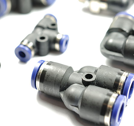
Fittings come in all shapes and sizes, and can be connected in a variety of ways. Shaped fittings ensure the effective design of a pneumatic system, with various unions and adaptors to reduce or increase the pipe diameter, or provide a neat continuity across fittings.
The most common types of connection are:
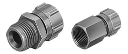
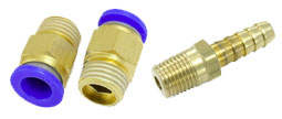
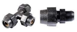
Compression fittings rely on compressive force to connect, and need no soldering to install. There are several ways to compress the fitting and most need no tools, but rely on a ferrule, ring or metal gasket to make the seal. Some types require a nut to be tightened, while others have a sharpened ferrule which bites the tube when compressed.
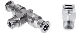
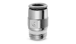
Threaded fittings have screw threads on the outer (male) or inner (female) surfaces, so that they can match other threaded fittings. Straight threads are the simplest, but tapered threads provide a better seal.
Push-in Fittings allow the tube to be secured by pushing it through a collet or grab ring and can be released simply by pushing a release collar.
The tube is pushed as far as it can go over a barbed end on the fitting, and secured by tightening a nut onto the combined assembly.
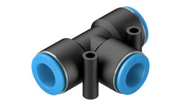
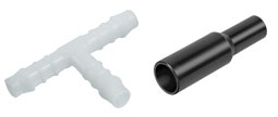
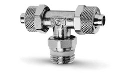
A T-shaped intersection connects three flow sections, allowing flow to be split apart or combined. Cross-shaped fittings do the same for four flow sections.
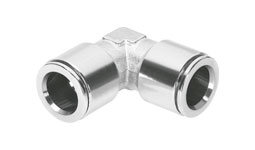
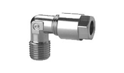
Elbow fittings change the flow direction at various angles without the risk of tube kinking. The most common elbow angles are 45° and 90°, but elbows also exist in 22.5°.
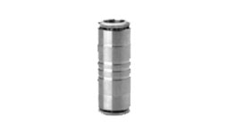
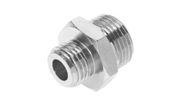
Reducer fittings connect two or more conduits of differing sizes.